Introduction: Battery Board for PALPi Game Console


Greetings,
Here's a fun little project, Battery Board for PALPi Version 6.
I recently created the sixth iteration of my PALPi Game Emulation Device Series, and it had a battery problem. I therefore prepared a simple battery board, which is a PCB that contains two lithium cells added into an SMD battery holder. The battery is charged by the onboard lithium charging IC, and the whole board fits on the back side of the PALPI lower body.
PALPI can operate with a backup of more than 3 hours thanks to the battery board, which is more than enough.
This article is about how this project was made, so let's get started with the build.
Supplies
These were the materials used in this built-
- Custom PCBs
- TP4056
- 1uF 1206 Capacitor
- 1K 0603 Resistor
- Dual 18650 Cell holder
- 3.7V 2900mAh Cell X2
- Rocker switch
- CON2 JST connector
- USB Micro Port
Step 1: About PALPi

Since last year, I've been working on a series of projects called PALPi, which is essentially a retro game emulation system built from the ground up using a Raspberry Pi as the system's brain.
It has buttons that are attached to GPIO pins, and the main display of the gaming system, a PAL display, is connected to the Raspberry Pi.
The term "PALPI" refers to the PAL display that this system uses. Nearly all variants have an in-built battery that powers the entire device, making it totally portable and useful.
There have been six versions created so far; click on the links below to view their build instructions.
https://www.instructables.com/PALPi-Version-2-Big-Edition/
https://www.instructables.com/PALPi-V6-Retro-Game-Emulation-System/
https://www.instructables.com/PALPi-V5-Handheld-Retro-Game-Console/
https://www.instructables.com/PALPi-Lite-Edition/
https://www.instructables.com/PALPi-Version-2-Final-Edition/
https://www.instructables.com/PALPi-Retro-Game-Console/
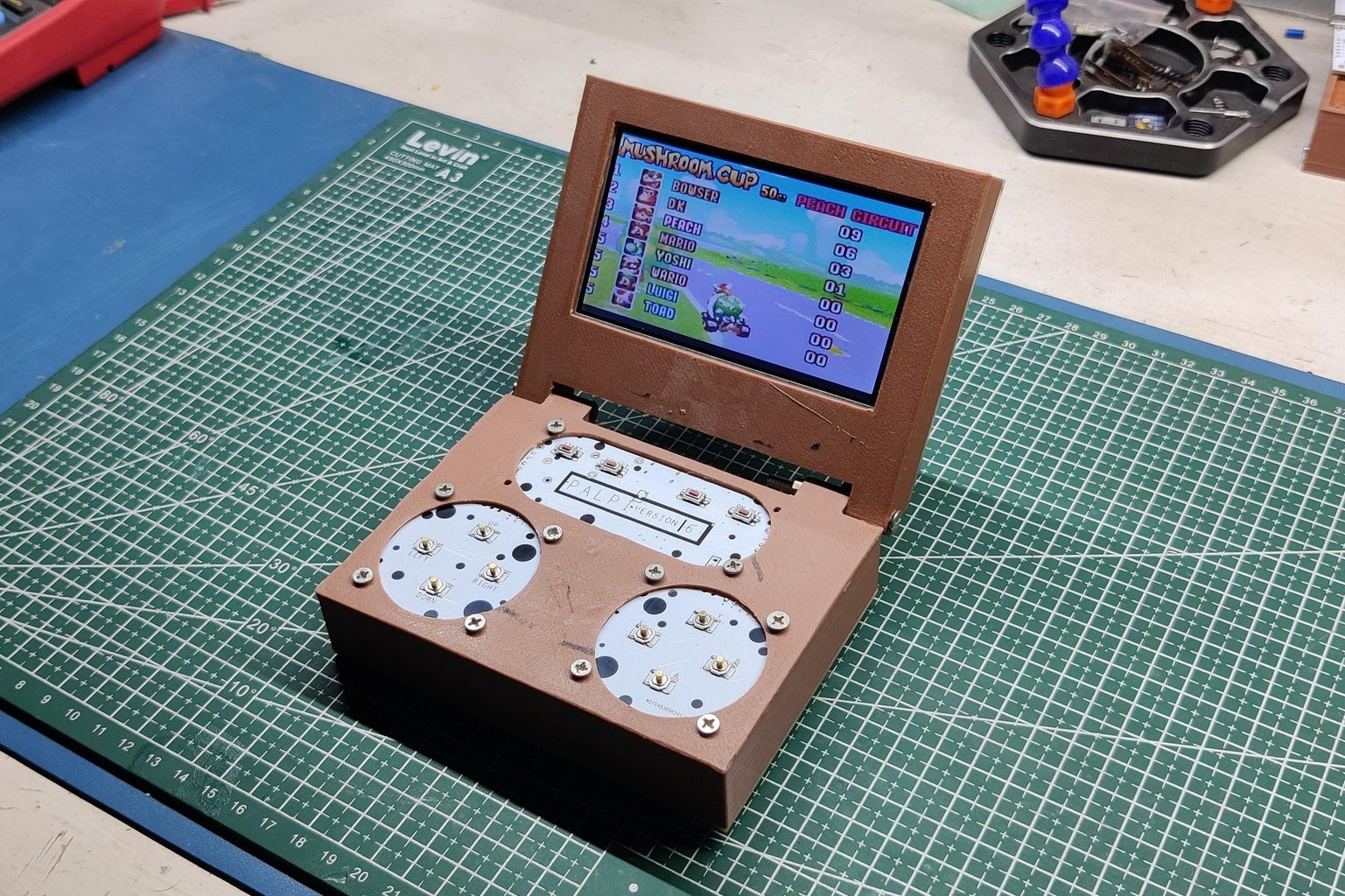
This most recent version, which was produced a few weeks ago, has an unique form factor that somewhat resembles the Gameboy Advance SP.
Step 2: Concept
In version 6, a single lithium cell was temporarily installed inside with hot glue in order to temporarily power the Pi and display. This quickly depletes the battery, and the resulting backup of the entire system was poor, with only 30 minutes of runtime.
A new PCB that holds two lithium batteries with an SMD Li-ion Cell Holder and also includes an additional TP4056 Charging IC that charges the lithium cells separately from the IP5306 setup was designed to address the IP5306 setup's tendency to restart the entire system when power is plugged in for charging the Cell. This resolved the Pi's tendency to restart when power was plugged in from the IP5306 side.
The concept of a battery on a PCB was ideal for this project because it acts as both a battery pack and an enclosure lid.
Step 3: Schematic-PCB
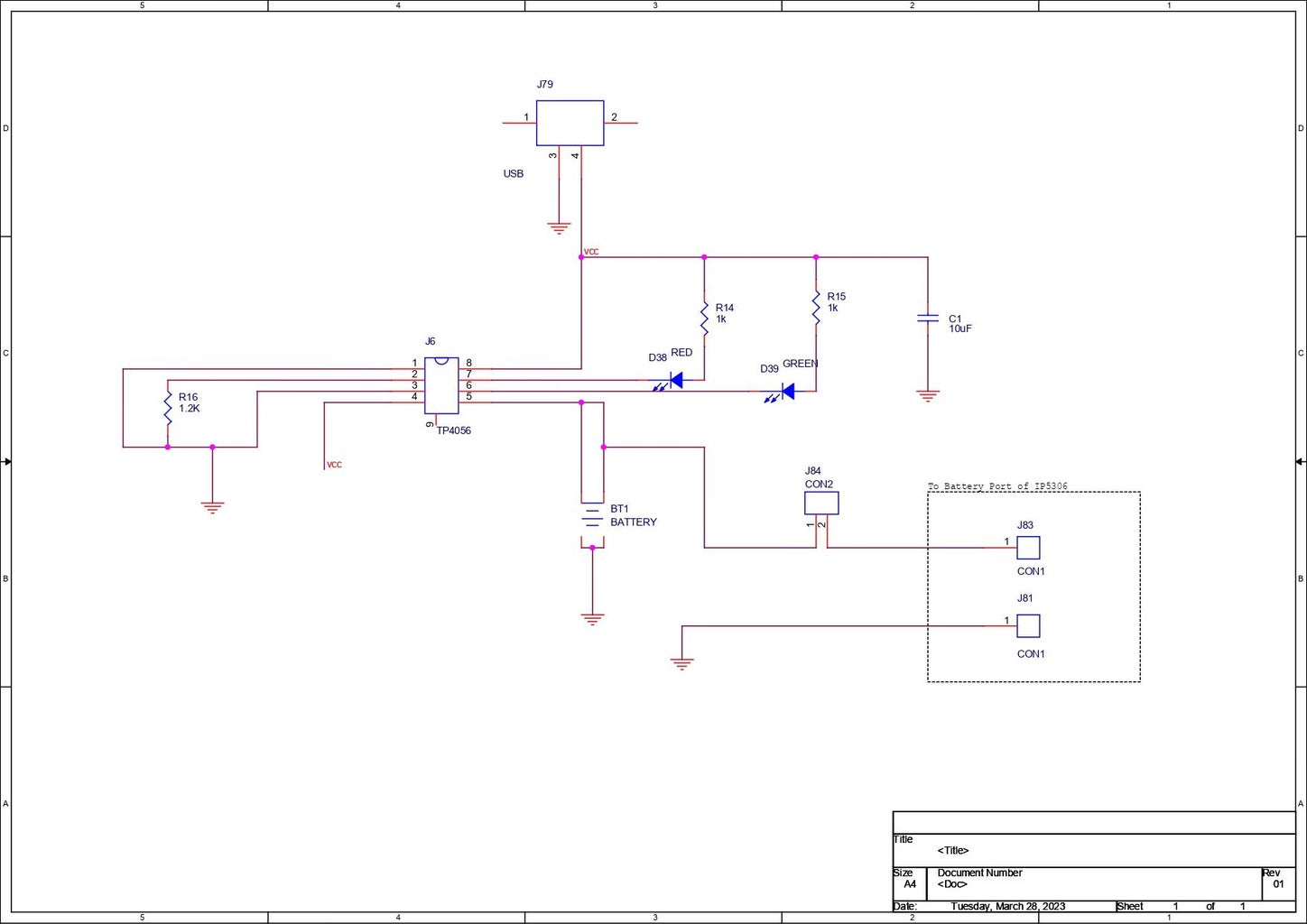
The TP4056 is a popular integrated circuit (IC) used for charging single-cell lithium-ion or lithium-polymer batteries. It is a low-cost and efficient solution for charging batteries in a variety of portable electronic devices, such as smartphones, tablets, and portable speakers.
The TP4056 IC includes a built-in power MOSFET that allows it to control the charging current, voltage, and temperature of the battery. It also features a constant-current/constant-voltage charging mode that ensures safe and reliable charging of the battery.
Some key features of the TP4056 IC include:
- Input voltage range: 4.5V to 5.5V
- Charging current: up to 1A (adjustable via an external resistor)
- Charging voltage: 4.2V (fixed)
- Trickle charging current: 130mA (fixed)
- Automatic recharging: if the battery voltage drops below 4.05V, the TP4056 will automatically restart charging
- Overcharge protection: if the battery voltage reaches 4.2V, the charging will stop automatically to prevent overcharging.
- Over-discharge protection: if the battery voltage drops below 2.4V, the TP4056 will automatically terminate the charging process.
- Thermal regulation: the TP4056 has built-in thermal regulation that limits the charging current if the temperature of the battery exceeds a certain threshold.
Overall, the TP4056 is a flexible and dependable integrated circuit that may be utilised in a variety of battery charging applications. In this situation, TP4056 serves as the primary battery pack charging IC.
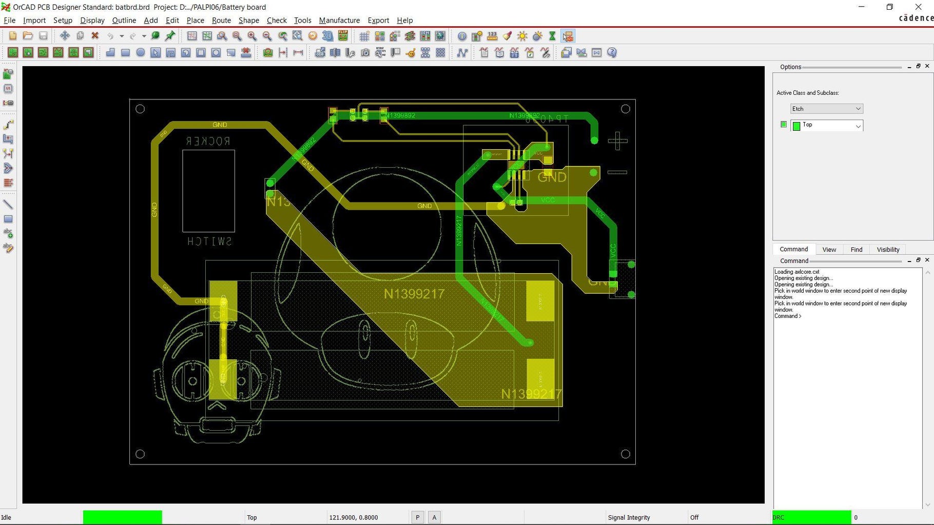
In order to create a board file, the PCB schematic was exported into netlist and converted to the PALPi Lid dimensions and hole location.
Also, we put a slot into the PCB so that an SPST rocker switch may be mounted there to disconnect power to the battery and the IP5306 Battery IN Port.
Step 4: PCBWAY
The gerber data of the PCB was exported after the PCB file was complete, and samples were then delivered to PCBWAY.
An order was placed for the PCBs with white solder masks and black silkscreen, as its looks pretty cool in general.
The PCBs were received within a week, and they were excellent, as expected.
As a leading China PCB manufacturer, PCBWay offers one-stop PCB manufacturing services,
ranging from raw material and electronic component procurement and in-house PCB fabrication to PCB assembly, testing, and shipping.
Check out PCBWay service for getting great PCB service at a lower cost.
Step 5: PCB ASSEMBLY
- Board Assembly Process begins by first adding solder paste to each component pad one by one.
- Next, using a tweezer, we pick and position each SMD component in its designated location.
- Following that, we carefully lifted the entire circuit board and set it down on the SMT Hotplate, which heats the PCB from below up to the solder paste melting temperature. As soon as the PCB reaches that temperature, the solder paste melts, and all the components are connected to their pads.
- Next, we add USB Port and CON2 JST connector in their place and solder their pads using a regular soldering iron.
- after adding header pin, we add rocker switch in its slot on the PCB and add the JST wire harness in the CON2 connector.
Circuit is now completed.
Step 6: Power Source and Testing
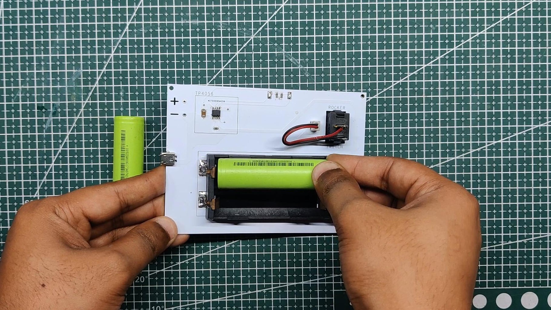

We put two Li-ion cells of 3.7 volts and 2900 mAh each into the battery socket in the right polarity and then measured the voltage across the output pins.
There we get the battery voltage, which is disconnected by the rocker switch.
The TP4056 IC charges both cells, and throughout the charging process, blue light glows, and when it gets fully charged, green light turns on and blue light turns off.
Step 7: FINAL ASSEMBLY
- The PALPi is prepared as we start the assembly process. We glue two wires to the positive and negative ports of the battery connector on the IP5306 IC.
- The battery board's positive and negative wires are then soldered together.
- Once the wire has been soldered, turn the circuit around and attach the board to the back of the enclosure using four M2 screws.
- The assembly is now complete.
Step 8: RESULT

Here is the finished product, a PALPI V6 with an in-built battery board that completes this project.
PALPI performs as it should, and the battery powers the device flawlessly.
I played a couple games on it to test this setup thoroughly, and the battery lasted for three hours, which was acceptable.
Check out the PALPI V6 built guide to read more about this project-
https://www.instructables.com/PALPi-V6-Retro-Game-Emulation-System/
Do leave a comment if you need any help regarding this project.
This is it for today folks.
Thanks PCBWAY for supporting this project, you guys can check them out if you need great PCB and stencil service for less cost and great quality.
And I'll be back with a new project pretty soon!
This is an entry in the
Battery-Powered Contest


Comments
11 hours ago
I like electronics , go on :)