Introduction: Retro Battery Powered Bluetooth Speaker


A year and a half ago, I built an Arduino-based mini retro radio (Retro Arduino Radio). The reception to that project was very positive, and at the time I was very happy with the final product. But as time has gone on and, as my skills have improved, I wanted to take another swing at this project.
This new design has been improved in many ways. It's much easier, faster, and simpler to assemble. It is no longer a radio, but a Bluetooth speaker. Which, I feel, because very few people listen to FM stations any more, gives it a more mass appeal. No programming is required for building this. Making this an easy project for almost anyone who has access to the right tools. And best of all, it's battery-powered! So you can take it anywhere and listen to your favorite tunes.
Supplies

These are affiliate links to the tools and, parts that I used for this build. By no means do you need exactly the same tools that I used, but they are included for those who are interested.
Tools
- Creality Ender 3 Pro
- Prusa i3 MK3S
- Weller Soldering Station
- iFixit driver set
- Tap and Die Set
- Router
- Router Table
- Table Saw
- Flush Trim Router Bit
- Forstner Bit set
- Hot Glue Gun
- Wood Stain
- Polycrylic
- Camera used for photos
PARTS
Electronics
- Amplifier Board
- Bluetooth Module
- Lithium Battery Charger Module
- 10K Ohm Potentiometer
- Red 3mm LED
- 3.7 Volt Rechargeable Battery
- Push Button Switch
- 1k Ohm Resistors
- 3W 8 Ohm 50mm Speaker
- USB C Cable
Hardware
- Heat Shrink Tubing
- Small Gage Wire (I used an ethernet cable)
- M3 Hex Socket Head Cap Screws
- Super Glue
- Zip Ties
- 1/4" birch plywood
Filament
Software
- Fusion 360
Step 1: Printing the Parts


The first step to this is printing out the plastic parts on your 3D printer. I used two different printers to make these parts. All the black parts were printed on my Prusa in Esun PLA+. while the gray parts were printed on an Ender 3 Pro in HatchBox PLA.
The parts are as follows:
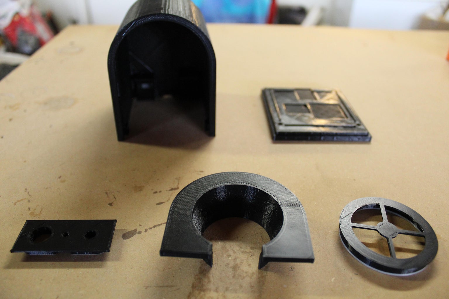
Black
- Outer case
- Base
- Button Plate
- Speaker Cover
- Speaker Holder
Gray
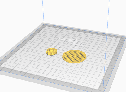
- Potentiometer Knob
- Speaker Screen
Those are just the colors I chose for my radio, but feel free to use whatever colors you want in your build.
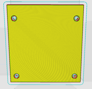
I spent a long time designing these parts so that they require a minimum amount of supports. In fact, there are only two parts that require any supports at all. They are the outer case and the base. The outer case only has one section that needs support, around the inside lip. The base needs four supports, one in each of the holes on the bottom. (SEE PHOTOS) All other components are simple and straight forward when it comes to printing, requiring no supports.


Step 2: Making the Face Plate


This step is very dependent on what tools you have access to. I'll explain how I personally did it, but you could do it in a number of different ways. Or just 3D print it.
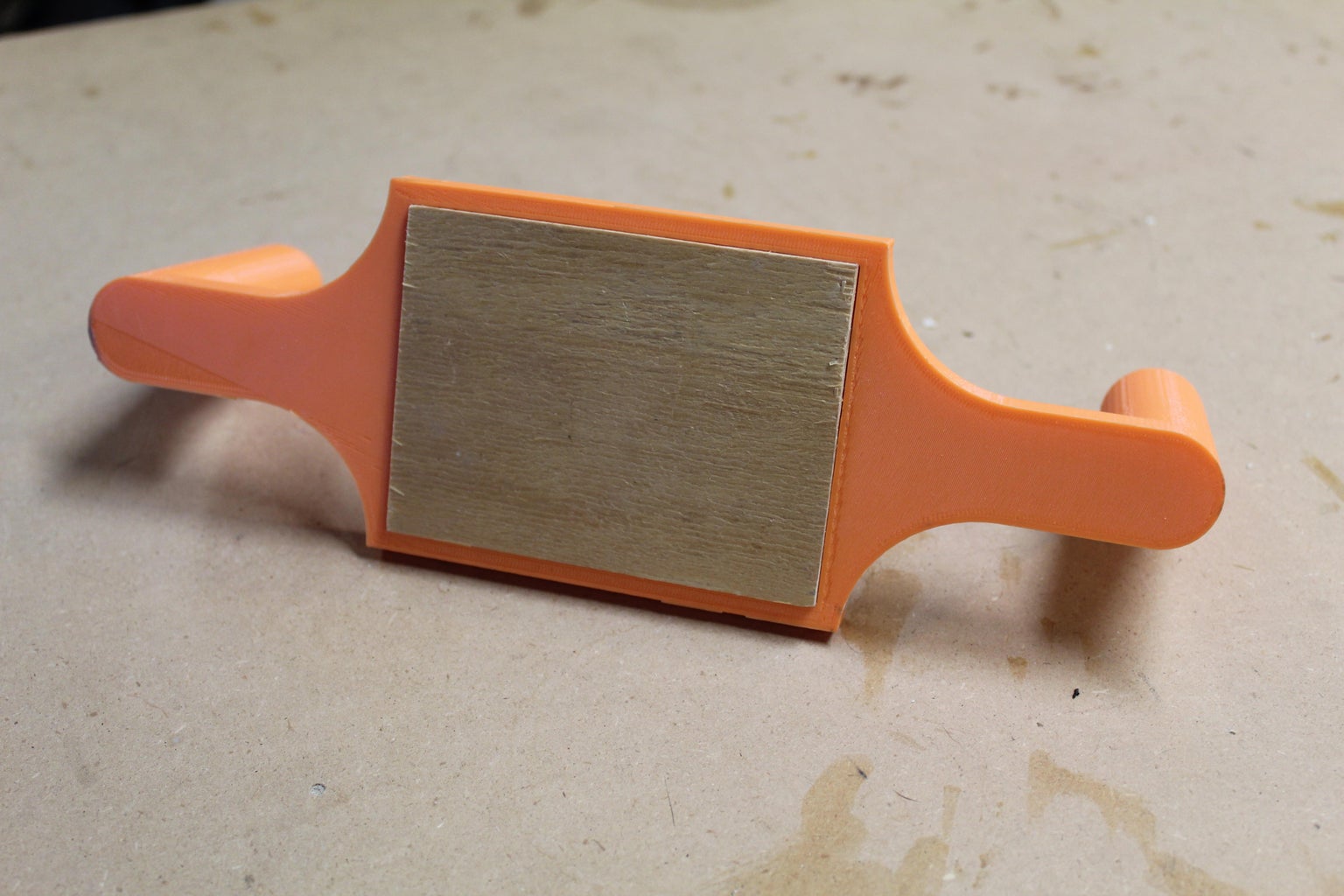
I started by coming up with a system for making a large number of face plates consistently, accurately, and quickly with the tools that I already have. So the method I came up with started by designing two different jigs in Fusion 360 so that I could place a piece of wood into them. Then use the jig as a guide for a router to make perfectly consistent cuts every time. I printed both of these jigs on my Ender 3 in PLA. (See the above photos for support placement)
After the jigs were printed, I got to work on making the faceplate itself. I started off by staining a sheet of 1/4" birch plywood with red oak stain. Then I gave it a coat of poly. After, I sanded smooth. I find it best to do those steps before cutting it down. Because it can be a much bigger pain polycoating and sanding a small piece of wood than a big sheet, However, I was making a large batch of these faces. If you are only making one, you might want to hold off on that step until after cutting it down to avoid staining good stock. Next, I cut the plywood into 3" by 4" squares using my table saw.
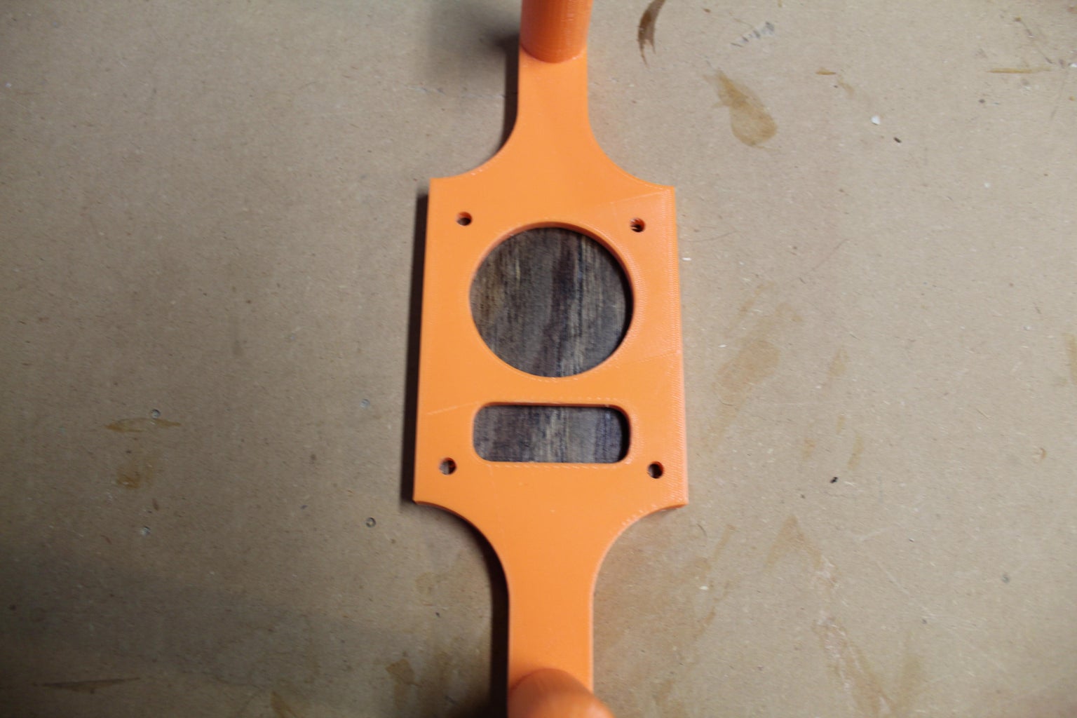
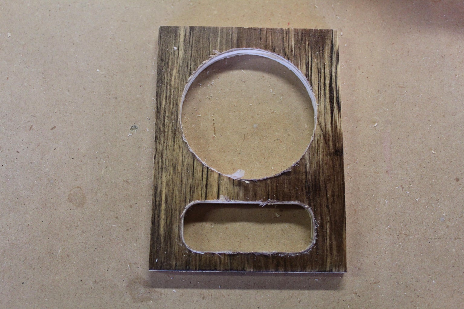
After the wood was cut down to size, I placed it into the first 3D printed jig( the orange one) and, moved over to my drill press. Using an 18mm Forstner bit, I removed as much material as I could from the wood in the window of the narrow opening. Then, using a 35-mm Forstner bit, I removed wood from the larger circular opening.
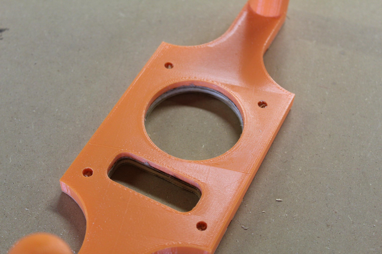
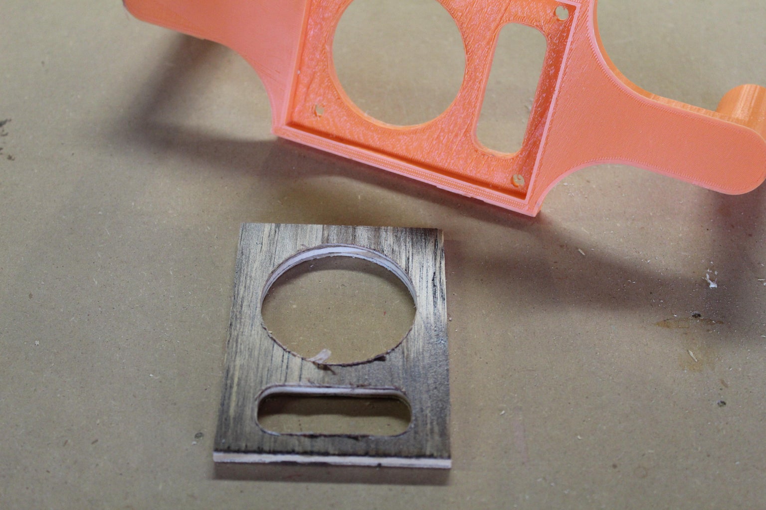
Once I have removed as much wood as I could using the drill press, I bring the jig over to the router table. Using a 1/4" flush trim bit and the edge of the jig as a guide, I remove the remaining wood from the openings. Now I can remove it from that jig and press it into our second jig (the gray one). Using the same router bit, I trimmed along the outside edge.
The only thing left to do is take it out of the jig and sand off any burs that might be there.


Step 3: Placing the Electronics


There is no custom circuit board for this project. It is all off-the-shelf components. Which makes it relatively simple to work on when compared to the circuit of my old retro radio design.
The first thing that you are going to want to do is take some CA glue and place just a small drop onto the center of each of the detents on the base plate. Than Following the above photo, place the charging board, AMP, and Bluetooth module into each detent on the glue. NOTE: The direction of the board matters. The USB C connector on the charging board needs to be facing outward. And the power inputs for the AMP and Bluetooth module need to be facing each other. Once this is done, set it off to the side so the glue has time to dry.
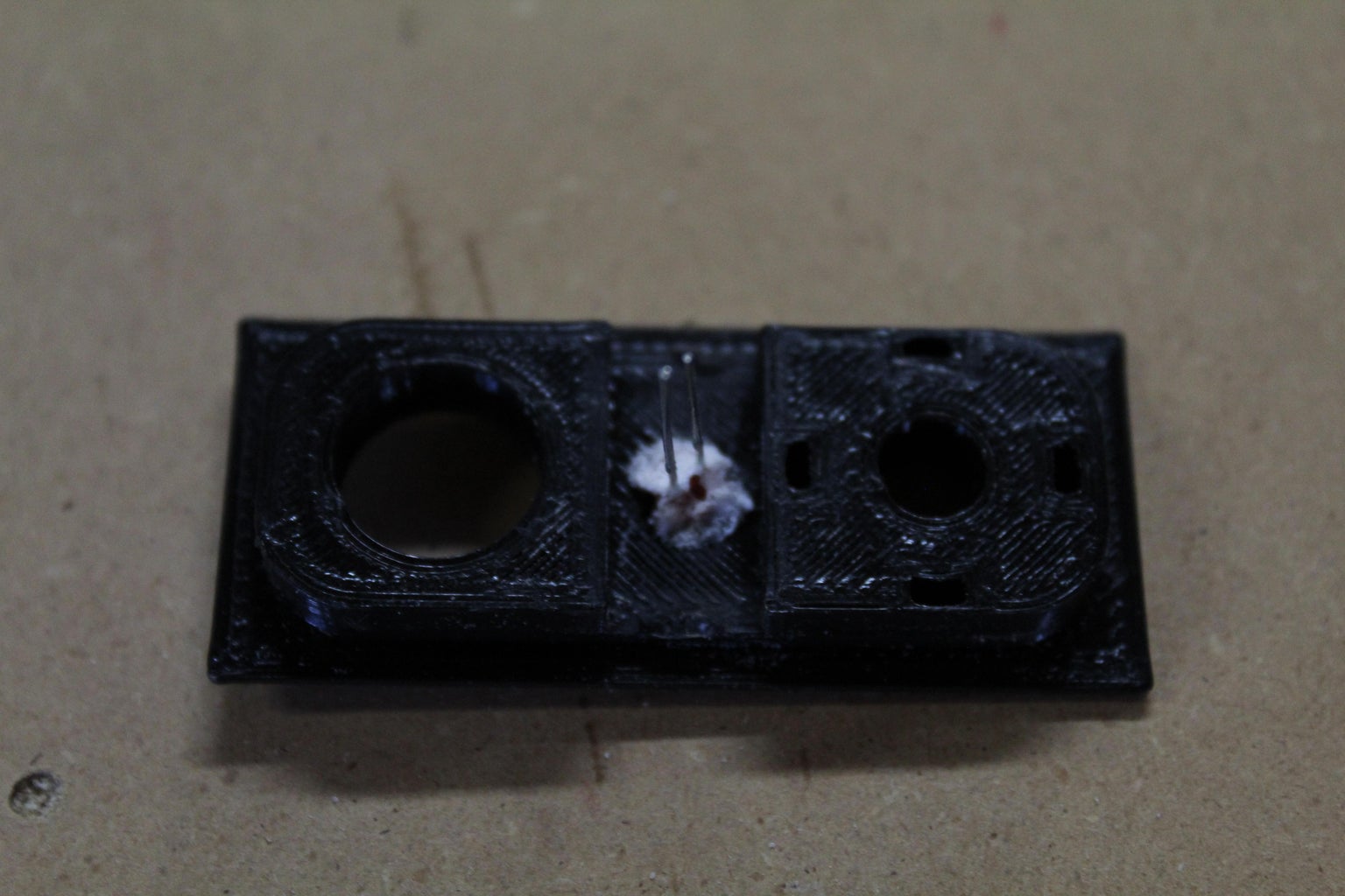
Next, take your button panel and press the 3mm red LED into the hole in the center. Add a drop of CA glue to hold the LED to the button panel. (Note: You can use a pinch of baking soda to instantly harden CA glue.) Now just set it aside to dry.
Step 4: Assembling the Button Panel
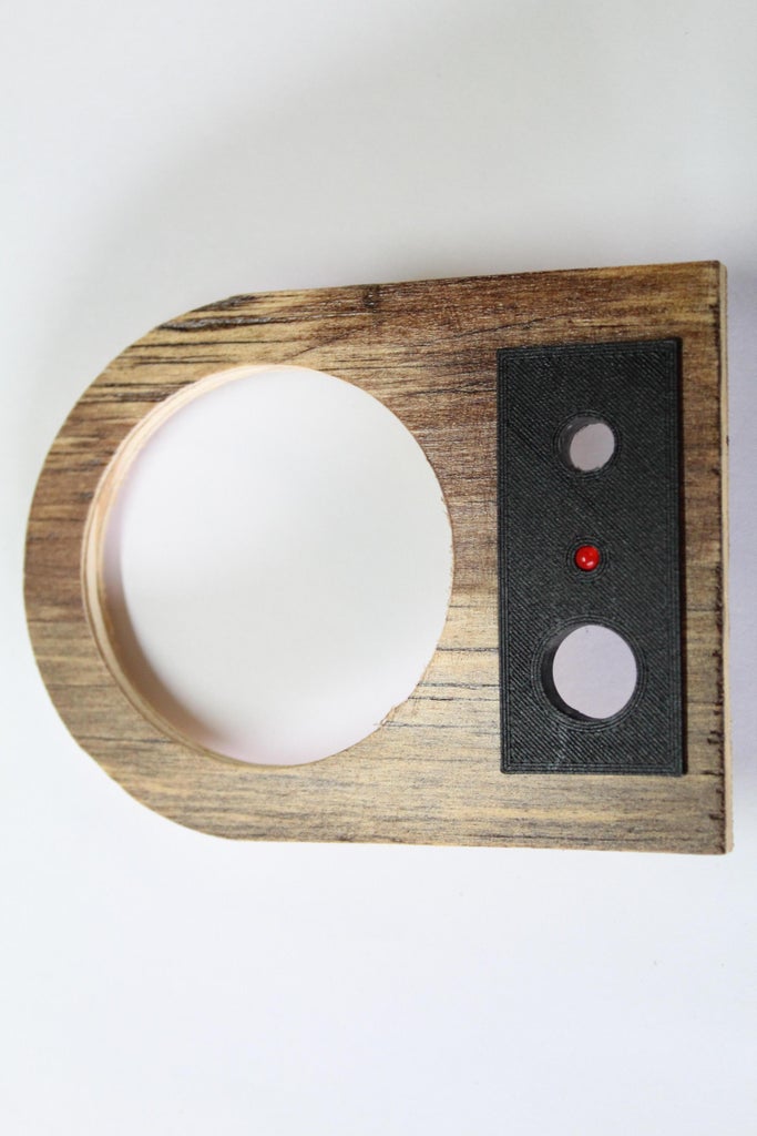


Take your button panel and press it into your face plate, making sure that the larger hole is on the left side. You can also add a few drops of super glue to ensure a strong bond, but I found that mine held just fine on a press fit. Next, insert the power button into the left hole and, from the back, press your 10K potentiometer into place, making sure the leads of the potentiometer are facing outwards.
Solder a 1K OHM resistor to one of the leads of the LED (I soldered it to the negative lead). Solder two 5" wires to the LED and 1K resistor. Cover your leads with a piece of heat shrink to avoid any shorts.
Solder three 5" wires to the leads of the potentiometer. I would recommend using three different colors to avoid any confusion.
My power button came with pre-soldered wires. But if yours did not, attach two 5" wires to the contacts.
Step 5: Soldering and Attaching the Battery


Solder a 5" wire to the positive and negative ends of the battery. Then set the battery into the grooves of your 3D-printed outer case. Place it in a way so that the negative end of the battery is facing to the left. Next, using a couple of zip ties, tightly attach the battery to the outer case.
This is not necessary, but it is recommended to tap the 4 holes located on the bottom of the outer case using a 3M tap.
Step 6: Soldering All the Components Together


For all of my connections, I either use thin bits of metal that I get from trimming the ends off resistors and LEDs or thin-gauge wire that I get from old Ethernet cables. I always find that it's cheaper to buy large Ethernet cables and cut out the wires that I need than it is to buy packs of thin gauge wire, and as a bonus, the wires come twisted together, making it a little easier to keep track of the wires when working on large projects.
The first step is to tie the power and ground of the AMP board and the Bluetooth module together.
On the Bluetooth module, you will need to tie the left and right channels together (marked L and R on the module). We are only using one speaker in this project, so we need the sound to be mono.
Attach a wire to the charging circuit ground connection (Marked: out-) and to the ground rail of the Bluetooth module and AMP.
Next, attach the wires from the potentiometer in this order.
- Top pin of the Pot is attached to audio out on the Bluetooth module.
- The middle pin of the Pot is attached to the right channel input on the AMP board (Marked R).
- The final pin on the Pot is attached to the ground connection on the AMP board, located next to the right channel input.
Now connect the wires from the LED on the button panel to the left channel output of the AMP board. We are not using the left channel of the AMP for audio in this build; instead, we are only using it to light up the LED to indicate that the unit is turned on. You can also attach the LED to the power and ground rails of the Bluetooth and AMP boards if you prefer or if, for whatever reason, the LED isn't lighting when attached to the left channel out.
Attach the power button by soldering one of the wires to the positive output of the charging circuit (Marked OUT+). And the other wire to the positive rail of the Bluetooth and AMP boards.
Next, the battery's positive and negative wires are connected to the charging circuit marked (B+ & B+).
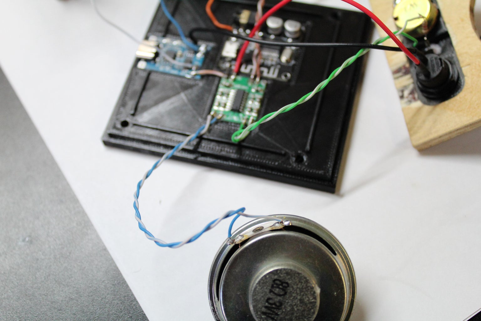
The final component to connect is the 8-OHM speaker. Once again, we use two 5" wires and attach them to the contacts on the back of the speaker. than solder the wires to the right channel output of the AMP. (Marked: R)
With all these components wired up, we are able to move onto final assembly.
Step 7: Final Assembly

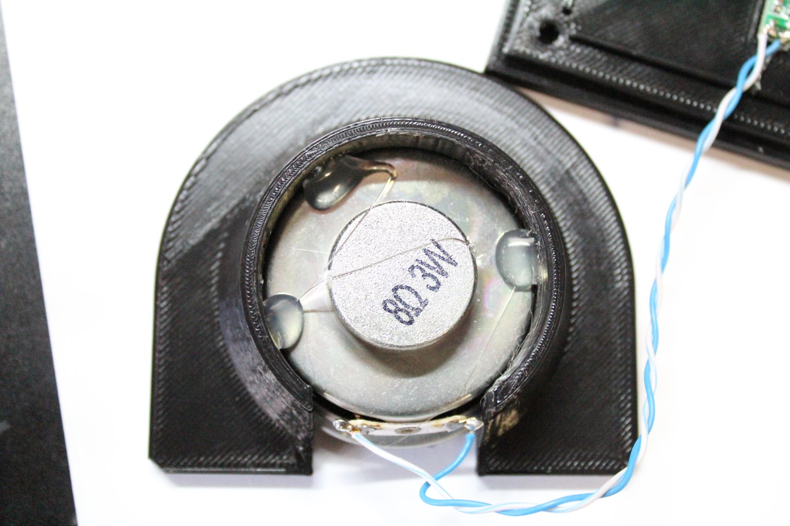


Take the 8 OHM speaker and press it into the speaker holder. It should be a nice press fit but, for a little bit of extra security I added a few drops of hot glue.
Put a small amount of super glue around the inter lip of the outer case. Slide the speaker holder onto the super glue and press down. It should snap into place and make a flush connection with the case.
With the speaker cover, add a small amount of superglue to the inside center as well as edge, and press the speaker screen into the speaker cover. This should be a press fit. the super glue is just there for extra security.
Once the glue on the speaker cover has dried, you can now press it into the face plate. This should be a nice press fit but, you could add a small amount of super glue if needed.
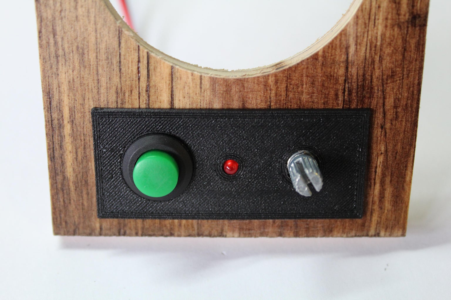
Now press the potentiometer knob onto the potentiometer. there is a small notch on the inside of the potentiometer knob the needs to line up with the slit on the potentiometer. This should be a tight press fit no glue required.
With the face plate now fully assembled. You can take it and slide it up into the outer case.
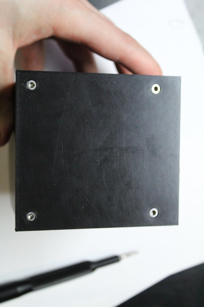
Finally take the base with the electronics and press it into the bottom of the outer case, making sure that none of the wires get pinched in the process. Note that the USB C port is facing out the back of the unit. Now lock in place using 4 3M screws.
Step 8: Testing


The only thing left to do is turn it on and give it a test drive.
The first thing to check is that when you press the power button, the red LED lights up.
- (If it doesn't, check the polarity of your LED to make sure that it is wired correctly. If that doesn't work, try hooking it up directly to the charging circuit. If it still isn't working, try swapping out your LED)
The next thing to test is the Bluetooth module. With the speaker turned on, search for the device with either your phone or computer and connect to it. With these Bluetooth modules, I have had two different device names come up: VHM-314 or BT5.0.
- (If the module doesn't come up when looking for it, check the wiring and make sure that it's getting power. There is a small blue LED on the module itself that will light up, indicating that it has power)
The last things to test are the volume control potentiometer and the speaker. With your phone or computer connected, start playing music. Then turn the potentiometer from left to right to verify that the speaker is working and that you have volume control.
- (If no noise is coming through the speaker, double check the wiring and make sure that it is connected properly. If that isn't working, check that you have it wired to the right channel output. If it still isn't working, make sure that the potentiometer is connected to the right channel input. If that doesn't work, try replacing the speaker)
- (If the volume is very quiet or distorted when twisting the potentiometer, double check the wiring on the potentiometer. If that doesn't work, try swapping out the potentiometer)
Step 9: Final Thoughts


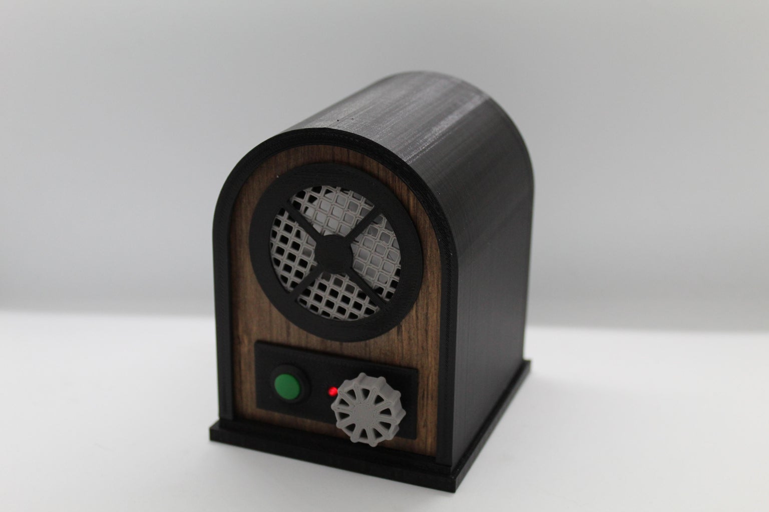


Over all, I am extremely happy with the final product. I spent a very long time coming up with a design that is simple to put together, good-looking enough to have on display, and practical for every-day use. I have found in my use of the unit that it gets decently loud and has a battery life of 8–10 hours. Also, the sound quality isn't anything spectacular. For some songs, the sound can get a little distorted at max volume. But that is to be expected from the budget parts that we used in this build. I think it sounds really good for what it is. Just don't go into it expecting a Bose-quality speaker.
This is a really fun and useful project to build. It's a great way to kill an afternoon, and I hope that if you decide to build it up, you have as much fun making it as I did. Thank you so much for reading!
Step 10: Social Media Links

This is an entry in the
Battery-Powered Contest


4 Comments
10 days ago
What a great project and I have to say those router jigs are simply a brilliant idea!
Reply 10 days ago
Thanks!
12 days ago
Thank you for writing such a nice blog with useful information. I hope you will share some more info.
https://hellodear.in
https://teatv.ltd/get-apk/
Reply 12 days ago
Thank you for reading!