
Introduction: PALPi Retro Game Console


Hey everyone what's up!
So this is my RecalBox based handheld gaming console aka the PALPi
Its name is PALPi because it uses a composite PAL Display.
When I was little I love playing games like Pokemon, contra, super Mario, Final Fantasy, and other games mostly on Gameboy advance and that game console that we hooked up with our CRT TVs to run great old stuff.
Well, nowadays we can just download the retro game ROM and open it up in an emulator and play that game on our laptop and mobile devices.
But as a maker, I wanted to do something different, so I prepared this handheld retro gaming console setup which is powered by a Raspberry pi zero, the OS that I'm using here is the Recalbox os. It's a decent Emulator OS that also comes with few preloaded games.
This whole setup is powered by an IP5306 IC which is a 5V 2A Constant Boost IC. It's used in a power bank circuit which is ideal for powering a Raspberry Pi zero.
In this Instructables, I'm gonna show you guys how you can set up this gaming console and make a Complete handheld Gameboy that can emulate any retro game that you can imagine.
(Also, the First Half of this project contains the breadboard version and the second half contains the PCB Edition)
Supplies
Material Required
These are the things that we need for this build
- Raspberry pi zero
- 16GB memory card (8GB will work as well but I wanted to add many games in it so I choose this instead)
- TV
- HDMI to micro HDMI adaptor
- 5V 2 A Charger/ PowerBank that can output stable 2A
- keyboard
- USB to micro USB adaptor
- RecalBox os image file/ Raspberry Pi Image Flasher
- Regular Pushbuttons
- Custom PCB
- IP5306 IC
- 10uf 0805 Capacitors
- USB Port
- USB Micro Port
- Li-ion Battery with CON2 Connector wire
- CON2 Connector
- 10k 0603 Resistance
- 2R 0805 Resistance
- Vertical Push Button
Step 1: Basic Setup

This is what I want to make, a cliche Gameboy layout.
I'm using a 4.3-inch display in this setup which is pretty huge if compared with a regular Gameboy screen so this setup size will be around 135mm x 140mm. On the front side, there's a display and buttons and on the bottom side, raspberry pi zero along with a boost converter circuit and a Li-Ion Cell will be placed. This Setup is a combination of PCB and 3D Printed Body which will be connected together via screws through the given mounting holes in the PCB.
Step 2: Setting UP the RecalBox

If Raspberry Pi is the Brain of this Project, then the RecalBox is the Heart.
I'm just making Hardware for this setup, there are already a bunch of other similar Gameboy stations based around Recalbox OS. The reason for that is simple, setting up RecalBox is a pretty easy thing to do and we only have to tweak few things in the OS to make certain things run. Here's how you can install the Recalbox for your raspberry pi!
- Download the Raspberry Pi imager.
- Select the right OS for your device, which would be RecalBox
- select your system which is Rpi0
- Raspberry pi imager will do your work of downloading and installing the RecalBox on the memory card.
After installing the RecalBox os, you need to plug your Raspberry pi setup with a TV and a Keyboard.
After booting the whole setup, our RecalBox works like a normal emulator.
Step 3: Schematic for Basic GPIO Wiring

This is the schematic that we have to use for GPIO Buttons. The buttons work when we pull down any GPIO Pin to GND.
Attachments

Step 4: Display and GPIO Controls


Let's talk about external display now, because this project apparently has 2 hearts, the second heart is the display.
when it comes to displays, we can find a bunch of them, both for HDMI ports and the ribbon cable one. they all work perfectly well but for this project, a 30$ display is not ideal so I bought a cheap car monitor which has a composite PAL Port.
Yes, I'm using a composite PAL Port here, I'm making a retro gaming console and the FPS is not really an issue here so composite is now my best friend, friendship ended with HDMI Port.
Before Hooking up the Car Monitor with Rpi, there was a small problem.
Car Monitor works with 12V and we require a 5V or 3.3V Display. So I open the monitor up and search about its ICs and found out that the display IC works with 3.3V and there's Buck Converter IC in this setup for stepping down the 12V to 3.3V for display. So I removed that IC and added VCC and GND on the Vout Capacitor and supplied 5V to this Display.
The display worked and now we can operate it with 5V.
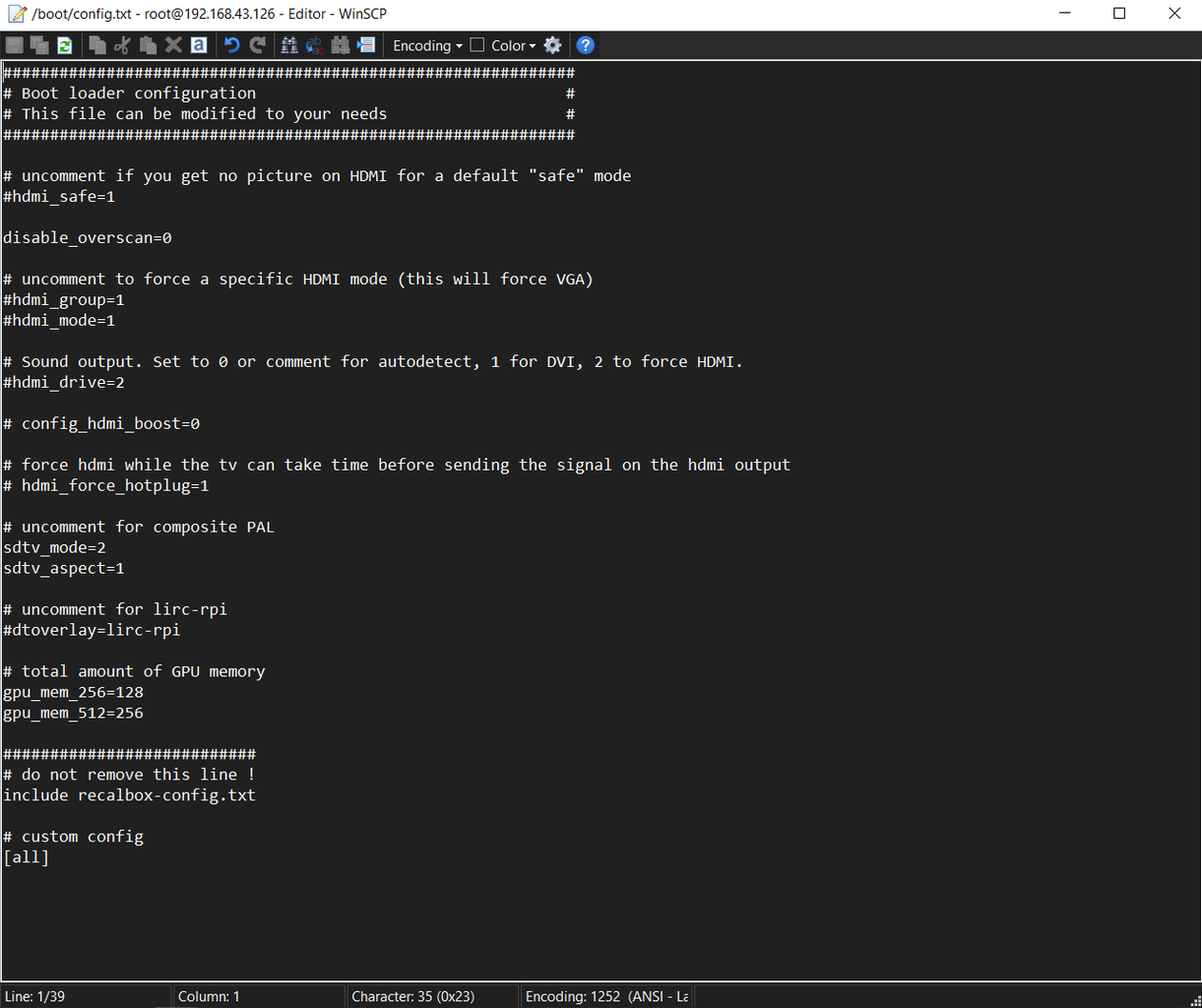
For running the Display with PAL composite, we need to edit few things in the config file. We will be needing a keyboard for entering the SSID and Password in the network setting.. (for connecting this with the win SCP).
Usually, we just connect the HDMI Display onto our Raspberry pi and it outputs its video signal but in our case, we need to set the SDTV output as default.
This is what you need to edit!
SDTV
go to boot>config.txt and change the default setting with this. We Remove # from sdtv_mode and add sdtv_aspect=1, also, we add # in front of HDMI lines. (Check the Attached Image of Boot/config.txt and just copy what's in it)
GPIO Control
go to recalbox>share>system>recalbox.conf
For Enabling GPIO Buttons, we only need to change two things in the above section.
set controller.gpio.enabled = 1 (It was 0 before) and change controller.gpio.args.map=1,2 to controller.gpio.args.map=1 (2 is second player controlls)
Just change your default setting according to mine (Check the attached D2 GPIO Controllers Image), then reboot the whole setup, and BANG, our Recalpi setup works with composite PAL and custom buttons!
Step 5: Setting Up Breadboard Version


Before setting up the Breadboard version, the raspberry pi pinout was completely normal but I'm using a custom GPIO adaptor (which I made from male and female header pins), when we add this adaptor on Raspberry Pi's GPIO Headers, Our Raspberry gets inverted (Upside down on a breadboard, Check the attached image)
Each button is added between the GPIO pin and GND, by pressing the button, the attached GPIO pin is grounded.
After wiring, we can connect this setup with an HDMI display and test whether the buttons are working or not.
Everything seems pretty good so after this, I disconnected the raspberry pi from HDMI Display and added the car monitor display video wire onto the raspberry pi's composite out port
- VCC will go to 5V
- GND to GND.
Now power the pi with any 5V 2A power source and BANG.
the composite display will work. (Do not forget to change the sdtv setting in the config file)
Step 6: PCB Version


This is the PCB version of the above breadboard edition/setup which had 13 Buttons connected with Rpi Zero.
The previous setup was powered by a Powerbank, which contains the IP5306 IC.
I searched about that IC on the Internet and found out that it's a power management IC for 3.7V Li-ion/Li-Po cells and it has a charge indication with battery percentage indicator and most importantly, High and Low cut of battery.
So I added the IP5306 minimal setup to my design and use it to boost a 3.7V Li-ion cell to 5V 2A for Raspberry Pi and Display.
I first Designed this whole Structure in Fusion360 and then use the PCB Layout from Fusion360 to model PCB Outline in My PCB Cad software.
I placed push buttons in the classic Gameboy Layout with an extra hotkey button.
Step 7: Ordering PCBs Via PCBWay!


After Finalizing the PCB, I uploaded its Gerber data to PCBWay's PCB Quote Page and ordered 5 PCBs in the Black solder mask.
I received These PCBs in a week which was really fast and I have to say, PCBs that I received was great as expected!
PCBWay you guys rock, Check Out PCBWay for getting great PCB Service for less cost.
The Next Step is the PCB Assembly
Attachments

Step 8: PCB Assembly


So After Receiving the PCBs, all that's left to do was the assembly process of this board which contains two major steps.
Step 1 is the SMD Components soldering and Step 2 is the THT Components soldering. For step 1, I will use my Hotplate to solder SMD components to the PCB but before that, we need to first apply solder paste to each component pad one by one.
After this, we need to pick and place each component by hand one by one carefully on their assigned location in the right order.
Next, we need to carefully lift this PCB and place it on an SMD Hotplate for Reflow. Hotplates heat the PCB from the bottom side up to the solder paste melting temp. when the solder paste melts, we need to remove the PCB from the hotplate and let it cool down for about 3-4 mins.
Now in Step 2, we add THT COmponents to this PCB which are USB Ports, Buttons, and battery connectors, then we solder their pads.
Also, I did order the Raspberry Pi GPIO Header Pins socket but it hasn't been delivered yet because of the pandemic lockdown here in India so instead, ill be using two header pins each contains 20 ports.
After soldering all the ports, our PCB has been completed.
Now we plug in the Lithium cell and add a USB Power Monitor to the USB Port and check the USB Output. (which should be 5V)
Now we add the main component of this project on this PCB which is a Raspberry pi zero W which already contains RecalBox installed with necessary changes done to the config file. check out this project page for more info about the config file or watch the video.
Our main Board already looks pretty awesome with the custom silkscreen done in front. Now we add this Circuit to our previously made Game controller body.
Step 9: Main Body Assembly


First, I added the Display on the 3D Printed Body with a Back support part which I also 3D Printed.
then I mounted the main Circuit on the main body with four self-locking M2 screws and then connect the display's VCC GND and PAL port with our Rpi and CIrcuit.
And our Setup is complete for now. We turn ON our setup by pressing an ON-OFF vertical button, Recalbox boots normally like it should and our buttons are working. Now let's play POKEMON EMERALD on this game controller.


Step 10: Result

Step 11: ADDING More Games


To add more stuff, we first need to download the custom ROM of any game you want to play on this game console. For example, I downloaded Dragon ball Advance Adventure. then we first need to connect the Recalbox to our WIFI router.
- go to the Settings>Network Settings, and add your WIFI Credentials.
- after adding the SSID and Password of your router, your raspberry pi will get connected with the internet and you will see its IP Address at top of the network setting menu.
- Open Win SCP on your computer, enter the raspberry pi IP Address on it, the user name will be root, and the password for the pi is recalboxroot.
- now go to this menu recalbox>share>rom, it contains all the ROM Folder, I wanted to add pokemon Emeral in it which runs on Gameboy advance so I had to copy-paste its ROM file in the GBA folder.
- now reboot your raspberry pi setup and open the GBA EMulator menu, and you will see the newly added game.
By doing the same, you can emulate so much good stuff in the Recalbox, just be sure to paste the game rom in its right emulator and that's pretty much it.
Step 12: What's Next?


This setup does work and I'm pretty happy with its performance. Right now, its display is OK, its not bad but its resolution is not very good.
The next version will have a better display, I haven't used a better display in this project because of cost reasons. Also, the Next Version will Feature a more slim and better version of the Overall PCB with a Display mounted on PCB or something similar and it will be powered by a Raspberry Pi Compute Module.
Not entirely sure but it will be better.
Leave a comment if you need any help regarding this project, check out this project video for more details.
Also huge thanks to PCBWAY for supporting this project. Check out PCBWAY for great PCB service for a relatively lower cost.
Stay safe And I'll be back with another project soon, Peace!

First Prize in the
Toys & Games Contest


6 Comments
1 year ago
The PCBA soldering videos are really helpful!
Reply 1 year ago
Thank you!
1 year ago
That's fun !
I'm interested in Compute version
thanks
Reply 1 year ago
Thanks, Compute Version is coming soon!
1 year ago
Wow! That's so cool!!
Reply 1 year ago
Thank you!