
Introduction: Rubik's Cube Solver


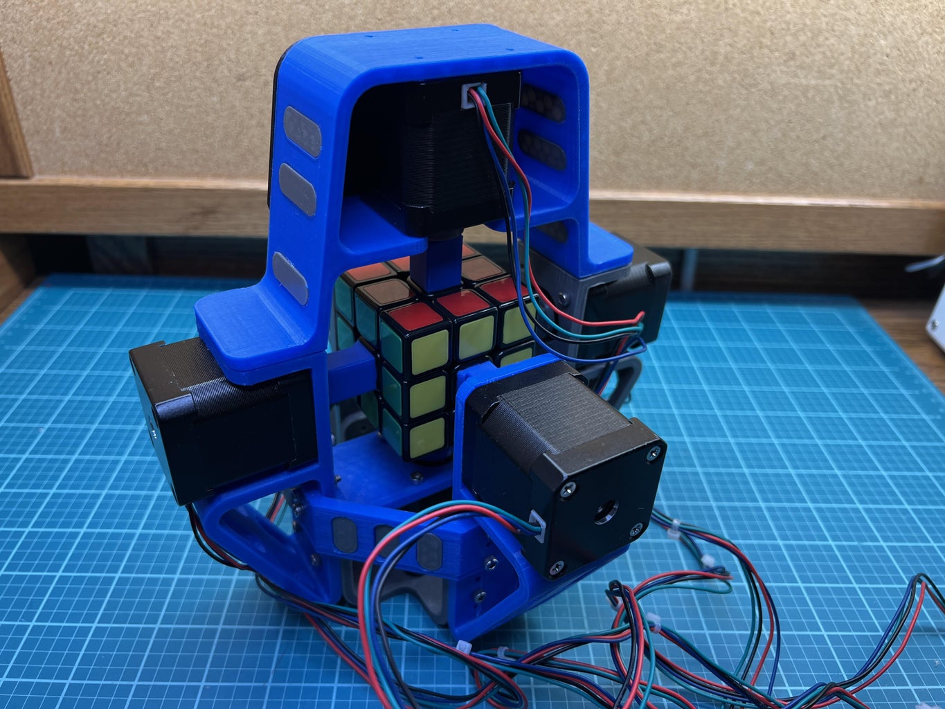


A couple of months ago I finally decided to learn how to solve a Rubik’s cube, and surprisingly it wasn’t as complicated as I thought. I can solve one in a little under 3 minutes, but considering that speedcubers can solve cubes in under 10 seconds 3 minutes seems exceedingly long. While practice does make perfect, spending years improving my cubing skills doesn’t seem that appealing. So, my next best option is to build a machine to solve Rubik’s cubes for me. Let’s build a Rubik’s cube solver!
Check out my Hackaday Page for more info on how I created this project.
Supplies


Tools/Supplies
- needle nose pliers
- wire cutters
- wire strippers
- 2.5mm allen wrench
- soldering iron and solder
- exacto knife
- hot glue gun and hot glue
- hammer
- gorilla glue
Parts ($270.94)
Electronics ($254.72)
- Teensy 4.1 Microcontroller
- Teensy 4.1 Ethernet Kit
- Nema 17 59 Ncm Stepper Motors (Bipolar)
- TMC2208 Stepper Motor Drivers
- 30V Bench Power Supply
- Mini Protoboard + Screw Terminals
- 100uF Capacitor 35V
- Male and Female Header Pins
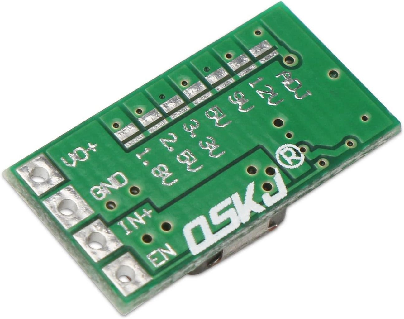
- 5V Regulator 4.5-24V Stepdown
- 22 AWG Wire
General Parts ($16.22)
Step 1: 3D Print the Parts


First, let's print the parts. There are 28 needed parts, 19 optional parts, and 14 total STL files. Some parts need to be printed multiple times. The optional parts just add to the visual aesthetic of the solver. Here are the parts
- stepper_motor_mount_a (x2)
- stepper_motor_mount_b (x2)
- cube_adapter_a (x4)
- cube_adapter_b (x2)
- base_plate
- top_stepper_mount
- bottom_stepper_mount
- stepper_motor_sleeve (x6)
- brace (x4)
- retainer_clip (x4)
- electronics_plate
- slot_insert_a (optional x12)
- slot_insert_b (optional x6)
- emblem (optional)
I printed all of these parts in PLA filament. I'd recommend using the following printer settings:
- 20% infill
- Auto-generated supports
- PLA (210° extruder and 45° bed)
The weight is about 316g. It took a cumulative 30 hours to print all 28 parts.
Rubix Cube Solver
Attachments
 stepper_motor_mount_a (x2).stl
- stepper_motor_mount_b (x2).stl
- cube_adapter_a (x4).stl
- cube_adapter_b (x2).stl
- base_plate.stl
- top_stepper_motor_mount.stl
- bottom_stepper_motor_mount.stl
- stepper_motor_sleeve (x6).stl
- brace (x4).stl
- retainer_clip (x4).stl
- electronics_plate.stl
- slot_insert_a (optional x12).stl
- slot_insert_b (optional x6).stl
- emblem (optional).stl


Step 2: Assemble the Frame


First, let's assemble the frame. To do so, we'll first need to mount the four stepper motor mounts onto the base of the frame using the following:
- M3 x 16mm screws (x8)
- M3 locknuts (x8)
Next, let's attach the four braces to the frame using the following:
- M3 x 16mm screws (x12)
- M3 locknuts (x12)
Refer to the image to see which holes should have screws and which shouldn't. The slot inserts are optional
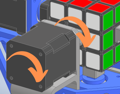
Step 3: Add the Stepper Motors


Now we'll add the stepper motors. Hammer each stepper motor sleeve onto the six stepper motors and screw five of the stepper motors onto the frame using (x20) M3 x 8mm screws. The sixth stepper motor mounts onto the top stepper motor mount with (x2) M3 x 8mm screws. The top stepper mount is the removable hat of the machine. In order for it to clip onto the machine you will need to glue 4 neodymium magnets onto the hat and 4 neodymium magnets onto the frame of the machine.
You may be able to get away with pressing the magnets into their slots, but you may need to use gorilla glue to make sure that they don't come out.
Step 4: Modify the Cube


In order for the Rubik's cube to fit into the machine we'll need to attach the cube adapters to each side of the cube. Make sure your cube is fully solved before doing this then take off the center tiles using an exacto knife. Remember that there are two types of adapters:
- cube_adapter_a (x4) (this adapter is open on one side)
- cube_adapter_b (x2) (this adapter is closed on all sides)
Cube adapters b attach to the red and orange sides of the cube. Cube adapter a attach to the blue, green, white, and yellow sides of the cube. Go ahead and label the color of each face on their respective adapter so that you know what the color of the center tile was before you took it off. When the cube is scrambled in the future this is how you will tell which side is which.
Notice the screws under each center tile. This will be used for tensioning the cube later on.
Step 5: Build the Circuit


Follow the schematic to build the circuit. I spread the electronics across 3 protoboards and mounted them onto a 3D-printed plate.
Bench Power Supply
- Set it to 24V
5V Regulator
- The teensy 4.1 and the logic boards on the TMC2208 drivers use 5V. The regulator steps down the 24V to 5V.
- Connect the positive and negative terminals of the bench power supply to the IN+ and GND pins respectively. The VO+ pin should output 5V once you adjust the voltage using the potentiometer on the regulator and a voltmeter. You can also use fixed output rather than the potentiometer.
Teensy 4.1
- The teensy 4.1 microcontroller is where the drivers and ethernet kit connect to.
- You must cut the 5V trace on the teensy that connects the USB 5V to the Teensy 5V. We will power the teensy with the bench power supply using the 5V regulator. This trace to cut is shown in the last image. Double-check that the connection is cut using a multimeter set to test connectivity.
Teensy Ethernet Kit
- The ethernet kit connects to the teensy and also connects to the LAN port on your router. You will need to assemble the kit by soldering the pins and the capacitor.
- Teensy 4.1 Ethernet Kit Instructions
Stepper Motors
- For now, don't connect the steppers to the drivers. This will be done in the next step.
TMC2208 Stepper Motor Drivers
- The drivers will connect to the teensy and stepper motors. As mentioned, don't connect the stepper motors to the drivers just yet.
- Set the reference voltage (Vref) of each of the drivers to 0.9V. This sets the current limit of the drivers to 0.64A. Here is a guide on how to do that.
- The VIO pin on all of the drivers connects to the + terminal of the bench power supply.
- The GND pin on all of the drivers connects to the - terminal of the bench power supply (there are 2 GND pins on each driver so it doesn't matter which one you use, they are both connected).
- You will need to add a 100 microfarad capacitor in parallel to the VIO and GND pins on all of the drivers. This is done to prevent voltage spikes from damaging the drivers.
- This project uses 1/2 micro stepping (400 steps/rev) so you need to connect the MS1 pin to 5V on all of the drivers.
- The VM pin on the drivers connect to 5V. This powers the logic boards on the drivers.
- Teensy Pin Assignments:
- pin 0 connects to the ENA pin on all of the drivers
- pins 1 and 2 connect to the STEP and DIR pins on driver #1
- pins 3 and 4 connect to the STEP and DIR pins on driver #2
- pins 5 and 6 connect to the STEP and DIR pins on driver #3
- pins 7 and 8 connect to the STEP and DIR pins on driver #4
- pins 9 and 10 connect to the STEP and DIR pins on driver #5
- pins 11 and 12 connect to the STEP and DIR pins on driver #6
Make sure that you have a common ground ie all ground pins on all components should be connected.
Attachments

Step 6: Assign Stepper Motors


In order for the solver to work properly we need to define each stepper as being either the top, bottom, front, back, right or left stepper and we also need to attach each stepper to its respective driver. Assigning the top and bottom steppers is quite obvious since there is clearly a top and bottom stepper. Assigning the front, back, left and right steppers is completely up to you. Assign one of the steppers as the front and then assign the others based on their location relative to the front stepper. Label the steppers after you assign them. Once this is done, connect the following steppers to the following drivers. Recall the driver assignments that were done in the previous step.
- Top stepper connects to driver #1
- Bottom stepper connects to driver #2
- Front stepper connects to driver #3
- Back stepper connects to driver #4
- Left stepper connects to driver #5
- Right stepper connects to driver #6
These stepper motors have four pins and two phases meaning two pins per phase. These four pins will connect to the M1B, M1A, M2A, M2B pins on each driver (refer to driver diagram in previous step). Two pins of the same phase will connect to the M1A and M1B pins while the two other pins, of the same phase, will connect to the M2A and M2B pins.
- To determine which two pins are in the same phase, connect any two pins of the stepper motor. If the stepper motor is noticeably harder to turn, then those two pins are of the same phase and the other two pins are of the same phase.
Now connect all the steppers to their respective drivers making sure that pins of the same phase are connected to either M1 or M2 pins. You may have to switch which phase connects to the M1 and M2 pins later. For now, it doesn't matter. Switching this changes the direction of the stepper.
Step 7: Setting Up the Webserver


I have made a web server to allow the user to set the initial configuration of the cube. This is why we are using ethernet on the Teensy 4.1. You'll need to plug the ethernet kit into a LAN port on your router. Now you need to find your IP address. First, install the three libraries here.
- AccelStepper library: drives the stepper motors
- CubeCentral library: displays the webserver
- CubeSolver library: solves the Rubik's cube
Now download the Arduino sketch below titled Find_IP_Adress and upload it to the Teensy. You should see your IP address printed on the Arduino Serial monitor. Now change the IP address in the sketch to the IP address you just found and reupload. Go to an internet browser and type in the IP address (ex. http://192.168.8.167/) and you should see the Cube Central web server. Right now, none of the buttons will do anything. This is what the buttons will be able to do once we upload the actual sketch (also labeled on the image).
- Clicking the name of the face will turn that side of the cube and update the cube display.
- Clicking any tile on the main display (the top left display) will change the color of that tile. This allows you to configure the cube.
- Clicking the next or prev buttons will allow show you a different side of the cube and allow you to configure it.
- Clicking the configure button and then refreshing the page will display the total amount of moves it would take to solve the cube in its current configuration.
- Clicking the start button will solve the physical cube.
- Clicking the reset button will revert all sides of the cube to their original color.
The web server has misinput prevention If you define a cube configuration that is not possible. Every cube has exactly 9 tiles of every color at any given time. If you define a cube negating this parameter, the start and configure buttons will be unclickable.
Attachments

Step 8: Upload the Program


Now it's time to upload the sketch. Download the Cube_Solver Arduino sketch, change the IP address to your IP address, and upload. Now when you go to the web server in your browser the buttons should work. Before you try to solve the cube you need to ensure that each stepper motor turns the right way.
- Cycle through each face of the cube and click the name of the face to turn that side of the cube. That stepper should turn 90 degrees.
- Looking from the back of that stepper motor, ensure that the stepper is turning clockwise. If it is turning counterclockwise reverse which phase connects to M1 and M2 on that stepper's driver.
- Repeat this for all of the steppers.
Now the solver should be ready to solve the cube. Scramble the cube, configure it in the web server, and place it in the solver. You must put the cube into the solver in a specific way.
- The adapter that you labeled red should be turned by the top stepper
- The adapter that you labeled orange should be turned by the bottom stepper
- The adapter that you labeled white should be turned by the front stepper
- The adapter that you labeled yellow should be turned by the back stepper
- The adapter that you labeled green should be turned by the right stepper
- The adapter that you labeled blue should be turned by the left stepper
When you click start, the solver should solve the cube.
In the Arduino sketch, the stepper speed is originally set to 1000 steps/sec. 500 - 1000 steps/sec is a good speed range. Anything outside of this is unpredictable. You can change the speed in the code if you'd like. I have been able to get solves at speeds up to 1380 steps/sec. Try this if you're feeling adventurous!
Attachments
Step 9: Common Issues

As the creator of this project trust me when I say that things won't always work the first time. Here are some of the issues that I have experienced.
- Stepper motor won't turn: Make sure the driver is connected properly. If the other drivers work, then you may have a faulty driver.
- The cube jams during the solve: First, you may want to tension the cube. The cube should have as little friction as possible. Second, you may want to reduce the speed of the steppers. Third, you may want to try adding the retainer clips that you printed. At slow speeds the retainer clips aren't really needed, but at faster speeds, they may be useful. They fit onto the adapters when you put the cube in the machine and prevent the cube from flexing.
- The solver runs but doesn't solve the cube: Sometimes the steppers slip and don't turn the cube. If this happens at least once during a solve, then the cube wont be solved. It is essentially missing a step in the solve. This happens occasionally. To prevent this, make sure the cube isn't too loose and consider reducing the speed of the steppers. At 500 steps/rev you rarely ever get slipping.
If your problems persist feel free to reach out to me.


51 Comments
4 weeks ago
This is an amazing design! My only idea to improve it would to try a different cube. You can get ones that are much easier to turn and don’t jam as easily. (The lightning bolts were a nice touch :) )
Reply 4 weeks ago
Appreciate the feedback. I agree although I think that the stepper motor itself also matters. Using stepper motors that have more torque, the quality of the cube shouldn’t matter at all. But with these motors, yes a higher quality cube would make a world of a difference.
5 weeks ago
Awesome! Great project, well explain and nice presentation.
5 weeks ago
This video is awesome! I really appreciate you sharing. Fantastic design! I adore your suggestion to use magnets to make it simple to remove the top.
7 weeks ago on Introduction
Hats off to you but I can't help thinking that's it's a bit counter intuitive. You buy a cube as a puzzle for yourself to solve then spend a fortune in making a machine to solve it? I don't get it
Reply 6 weeks ago
I would guess his motivation for doing this is the same either way.
The challenge!
Reply 6 weeks ago
The point is it's a puzzle for YOU to solve, not a computer,just don't get it, although I marvel at the technology involved, I'm sure there are other things you could do with the equipment that is useful
Reply 6 weeks ago
The OP said he already learned to solved the Rubik’s cube. What now? Chuck it in the garbage!
Is a puzzle simply not a challenge of figuring out how to make or do something?
Figuring out the mechanics is a challenge, so that’s like a puzzle.
Figuring out the electronics is also a challenge, so that too is like a puzzle.
Figuring out the software is a challenge, so that is like a puzzle as well.
So his project IS a puzzle. A multi-disciplined puzzle at that.
As they say, Different strokes for different folks.
Reply 6 weeks ago
You get it! The fun of the project was figuring out how to write code to solve a complex puzzle. As you said the project was all one big puzzle!
Reply 6 weeks ago
I totally get it!
I’ve had a long career of “solving” puzzles.
20+ years in electro-mechanical design of custom automated equipment.
I’m now writing code for various needs in the testing of microprocessors. Which is a really, Really, REALLY big puzzle. The databases I build have several million records mapping the logical schematic to the physical location on the chip.
They say - Do something you love and you’ll never work a day in your life!
I’ve been fortunate to live that
Reply 6 weeks ago
couldnt agree more
Reply 7 weeks ago
Two things. First, I bought a Rubik's cube several months before I even thought about doing this project. I initially just wanted to learn to solve one. Second, it wasn't that expensive for me. The estimated cost is high but that's only if you have to buy everything that I used. Since I had most of the parts, my only expenses were the stepper motors, drivers, and teensy.
6 weeks ago
This project wants me to solve rubik's cubes again
Reply 6 weeks ago
You should! They are so much fun.
7 weeks ago
Dude... MIT is on the phone and they want to talk to you!
Reply 7 weeks ago
Fool me once….
Reply 6 weeks ago
If you need some inspiration for version two, you should check out the MIT cube solver:
I think you're probably at the limit of those stepper motors. Anyway, good work!
Reply 6 weeks ago
Yep I actually included their machine at the end of my video but thanks.
Reply 7 weeks ago
Shock and awe 😲🤯😎throughout the entire video ... Definitely "MIT here I come"
💭🤔💬
6 weeks ago
I kind of want to favorite this project about 10 times. Maybe even a few more. Can't wait to see what you create next!