
Introduction: DIY Arduino Camera Robot (Motorized Pan Tilt Head)


Hello and welcome back to my channel! For the past few months I have been building a motorized system to move the camera when I shoot video footage for the videos that I publish on my channel.
The idea behind this project is to shoot footage with a very smooth and stable movement easily and without having to redo it many times, like I used to do when I did camera movements by hand. I had actually already built something similar back in June, that was made of a rotating base on which to put my tripod. The idea worked but the construction had many problems, so I decided to take another approach.
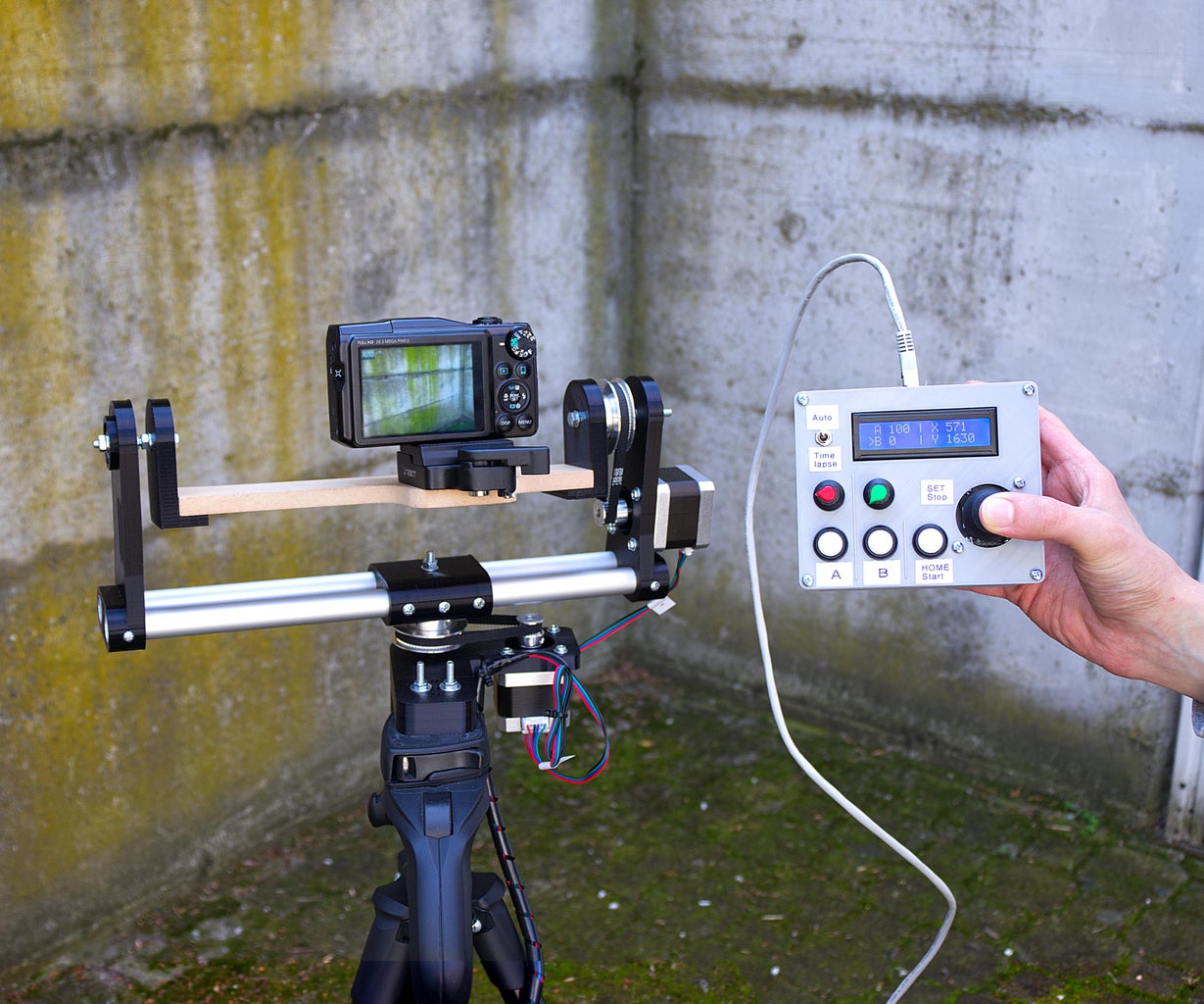
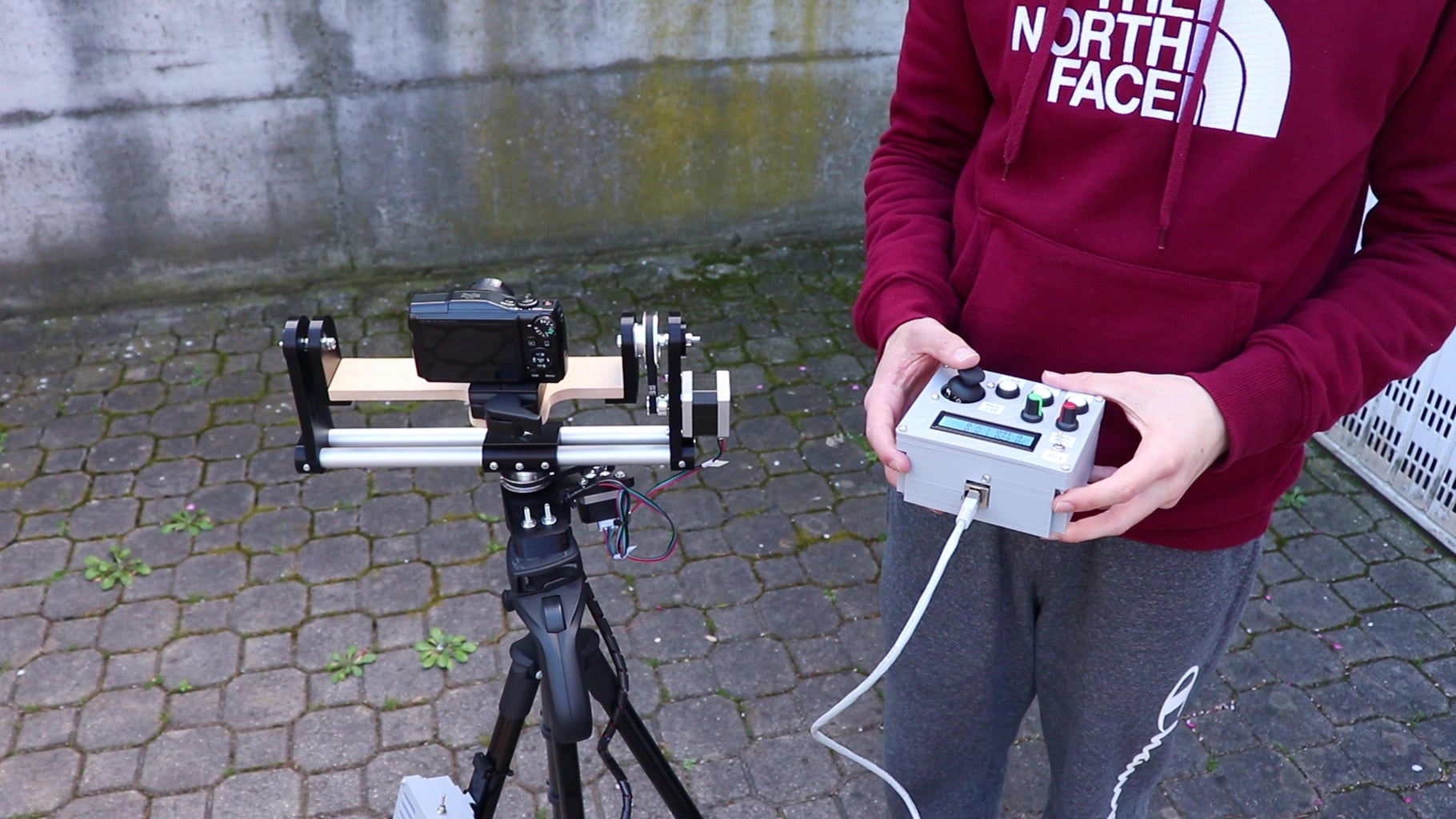
Anyway, the whole project started with the idea of moving the camera placed on the tripod using a remote control with a joystick. After solving many problems in the mechanical part I was able to do exactly that. Once the mechanical part was working I worked on the electronic part and wrote the code for the Arduino. The robot has so many functions that you can use to make great footage, such as an "automatic" mode in which you can save two positions and move the camera between them by just clicking two buttons, and a mode for making timelapses, that divides a camera movements into small steps and goes to the next step after every photo of the timelapse is taken, to create an amazing effect once the photos are sped up.
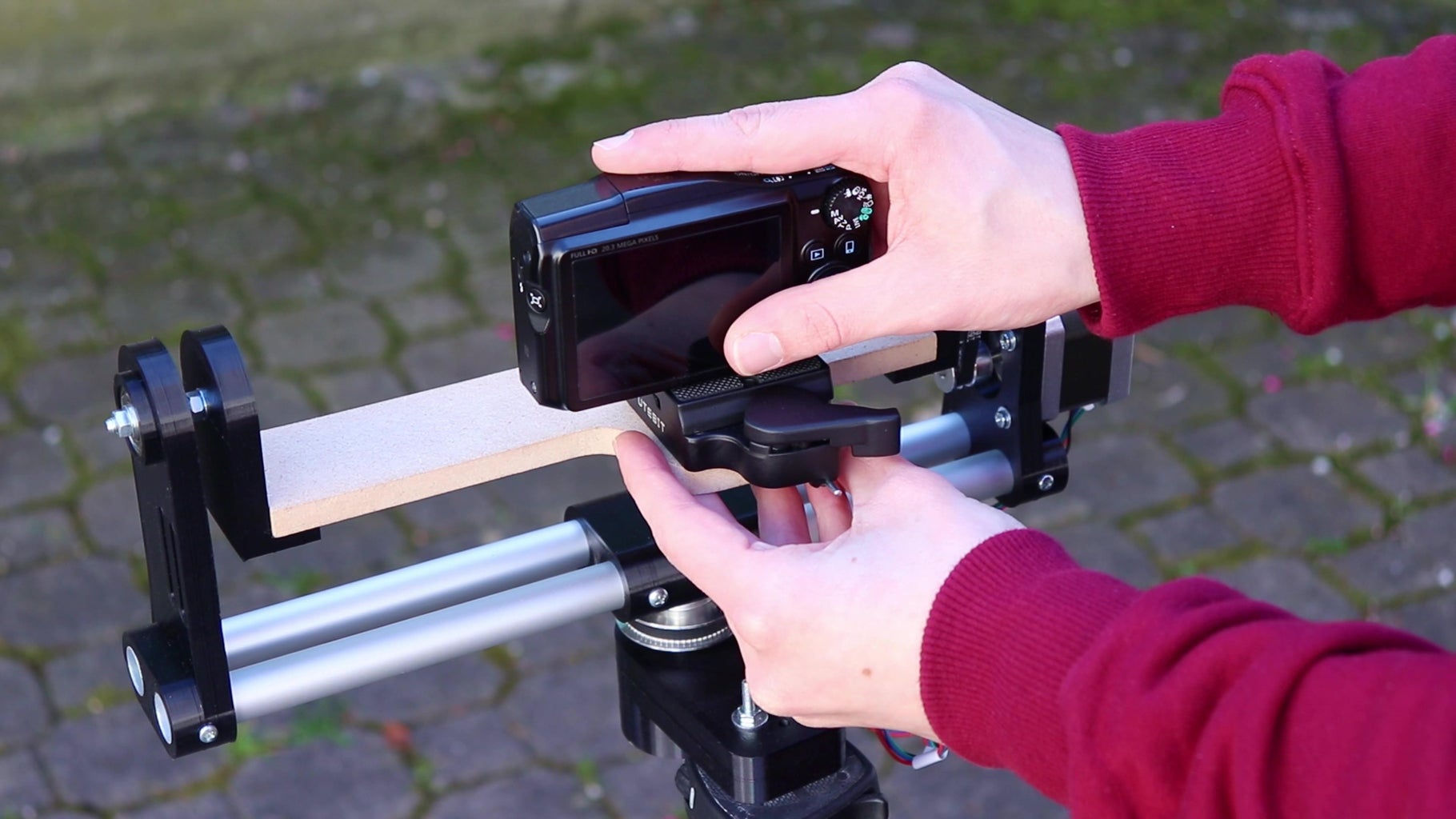
The camera robot is meant to be mounted on a tripod, and it has horizontal and vertical movement. The robot has a mount on top on which to mount a camera or smartphone.
If you want to see more about this project, how I built it and some videos made with this robot, check out the video on my YouTube channel (it has English subtitles). But now, let's get started!
Supplies
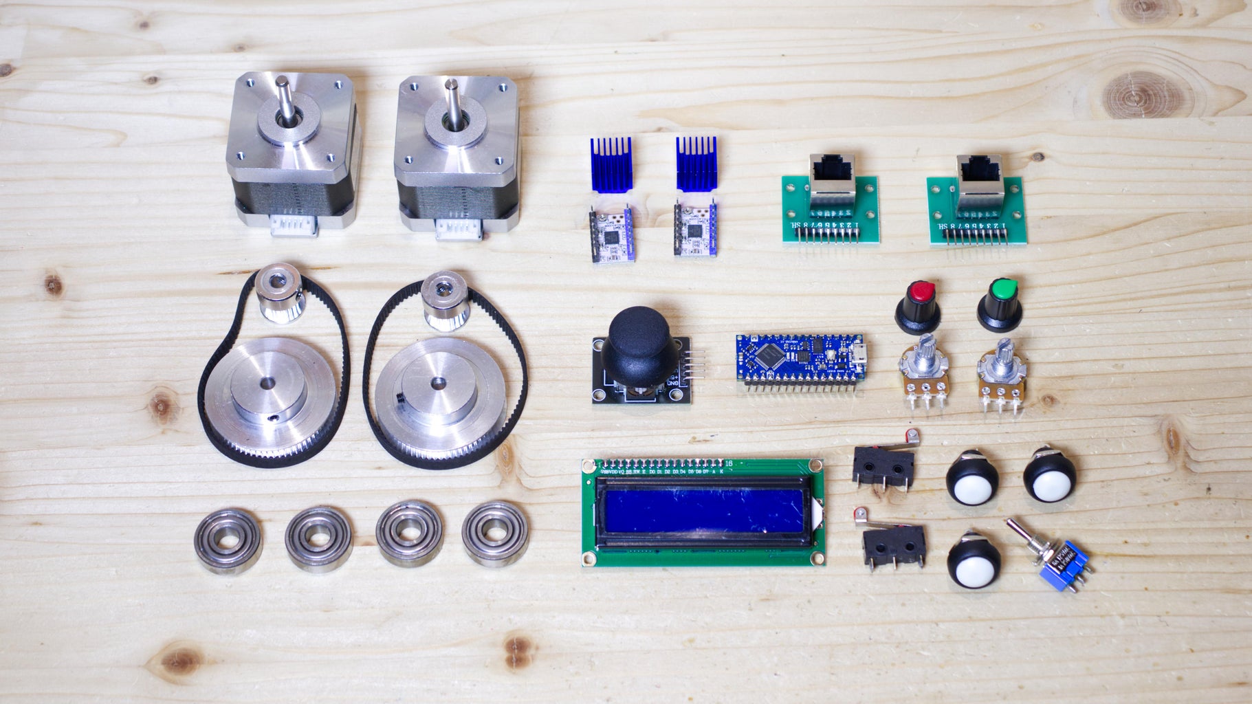
This project is quite complex and a lot of components were needed to make it, including screws, motors and electronics. We will need:
- Arduino UNO or other Arduino board
- 2 NEMA17 39 mm stepper motors with their cable
- 2 TMC2208 stepper motor drivers
- 2 100uf capacitors
- 2 sets of 60 teeth pulley, 20 teeth pulley and 200 mm belt
- Ethernet cable
- 2 RJ45 ports mounted on breakout board
- LCD display with i2c interface
- 3 momentary buttons
- Analog joystick with central button
- 2 10k potentiometers with knobs
- 3 positions toggle switch (on-off-on)
- 2 positions toggle switch (on-off)
- DC connector
- Perfboard
- Wires
- 2, 3, 4, 5 pins JST connectors (optional)
- 4 ball bearings (22 mm outer diameter, 8 mm hole diameter)
- 1 M5 40 mm bolt
- 1 M5 60 mm bolt
- M5 threaded rod
- M5 nuts and washers
- M3 bolts and nuts
- Self-tapping screws
- 16 mm aluminum tube
Tools:
- 3D printer with PLA filament
- Soldering iron
- Drill
- Wood hand saw
- Sandpaper
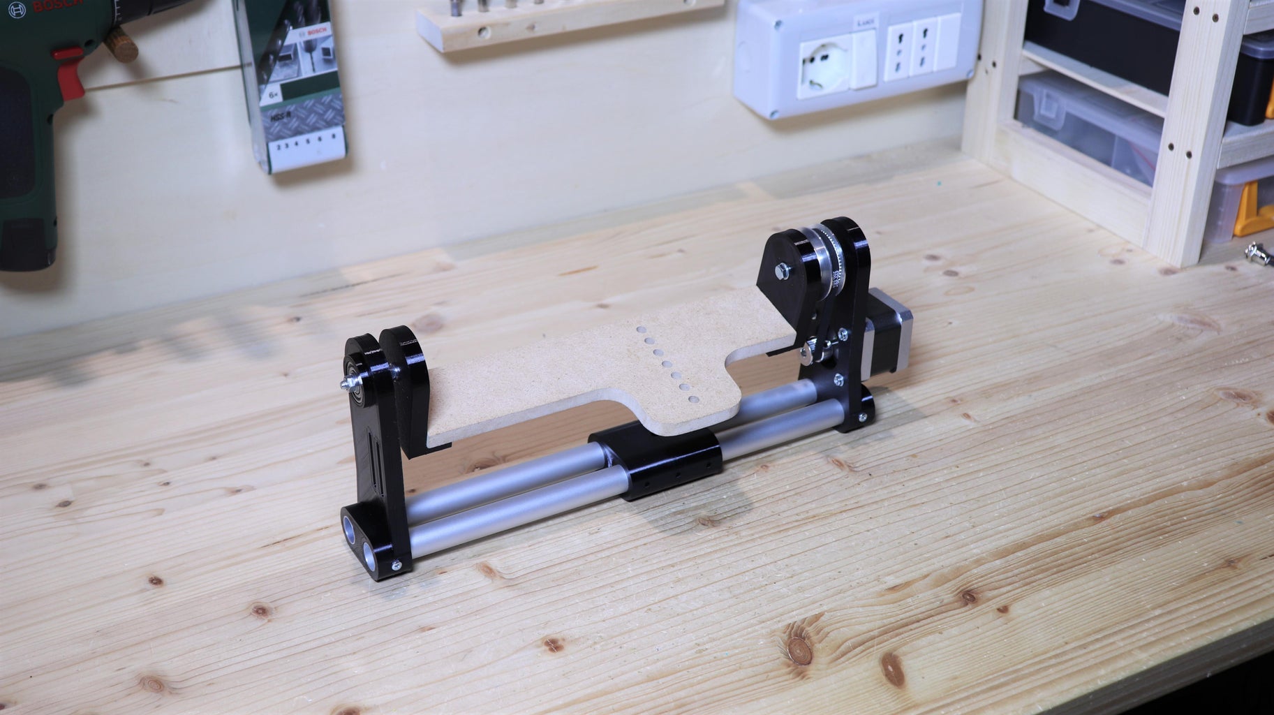
Step 1: Vertical Movement Frame
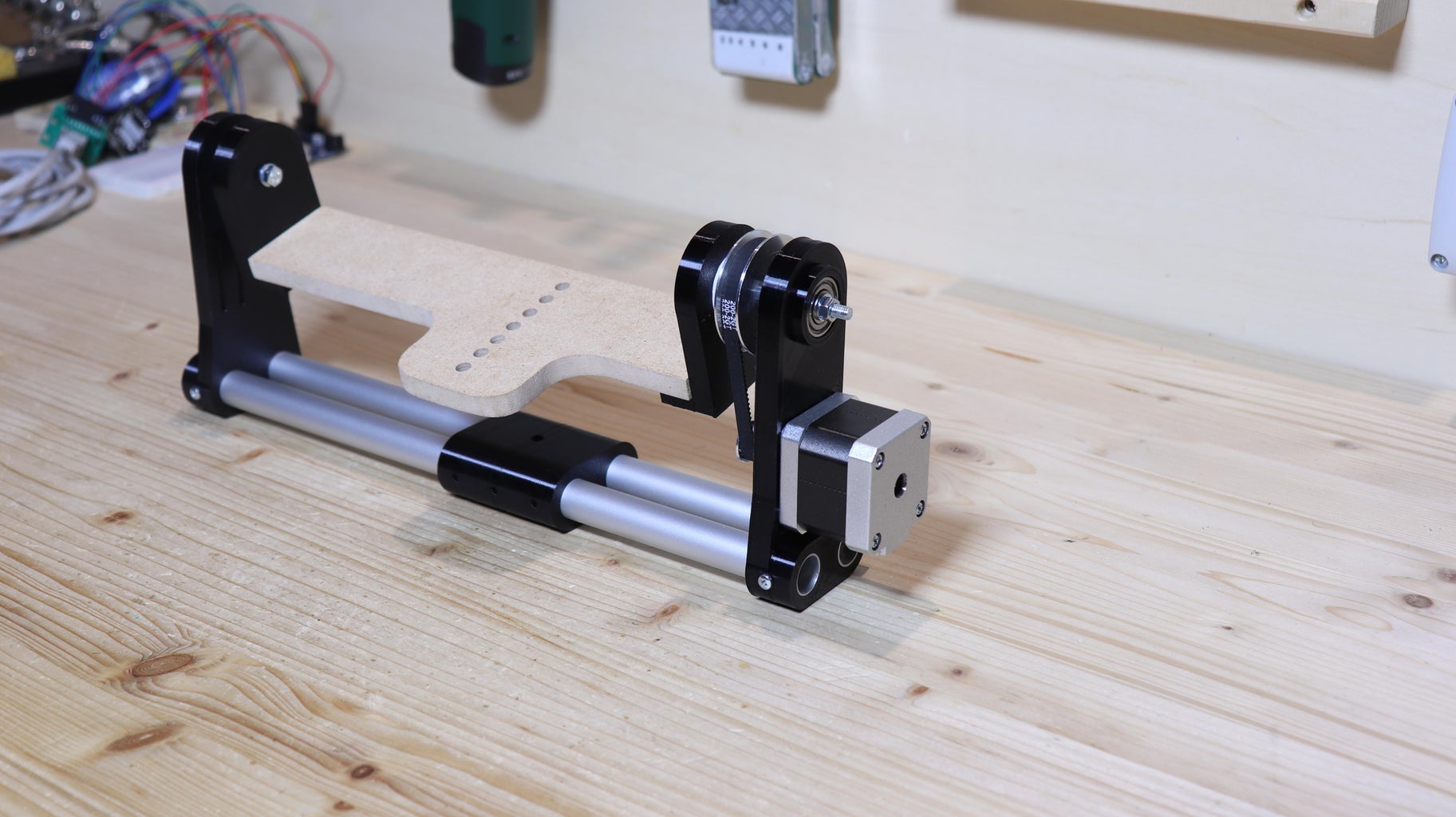
To make the frame of the vertical movement of the robot, I 3D printed the 3 pieces of which you find the stl file below, and finished them near the holes with sandpaper. Then I took two ball bearings and put them in the holes in the two sides of the robot. To hold the 3D printed parts together, I cut two 32 cm pieces of an aluminum tube. I threaded the two aluminum tubes into the holes in the two sides and the center piece, and attached them to the two sides with M3 screws, after drilling 3 mm holes. Then I took the stepper motor and screwed it with M3 bolts to the side that has the big hole and the small holes for the screws.
Camera robot vertical movement


Step 2: Camera Mount
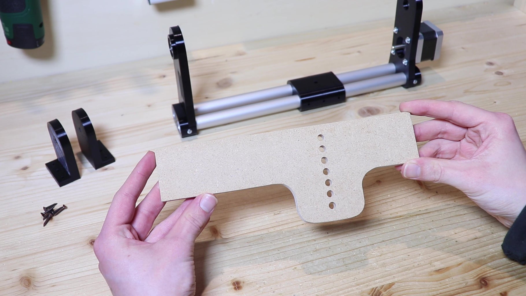
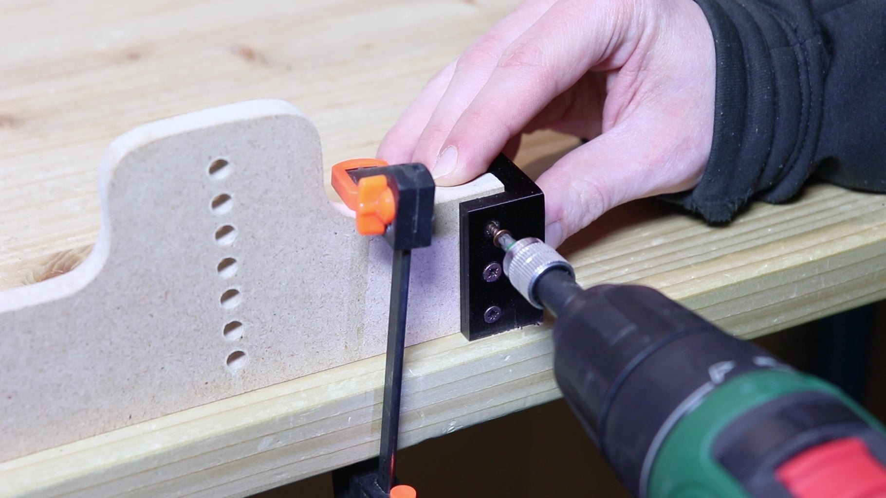

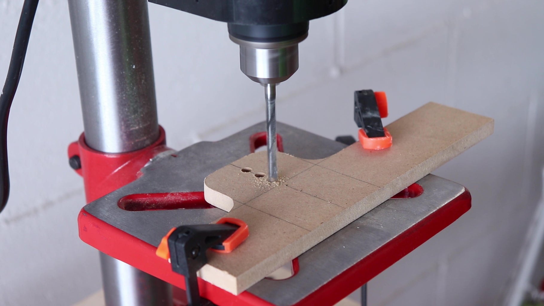
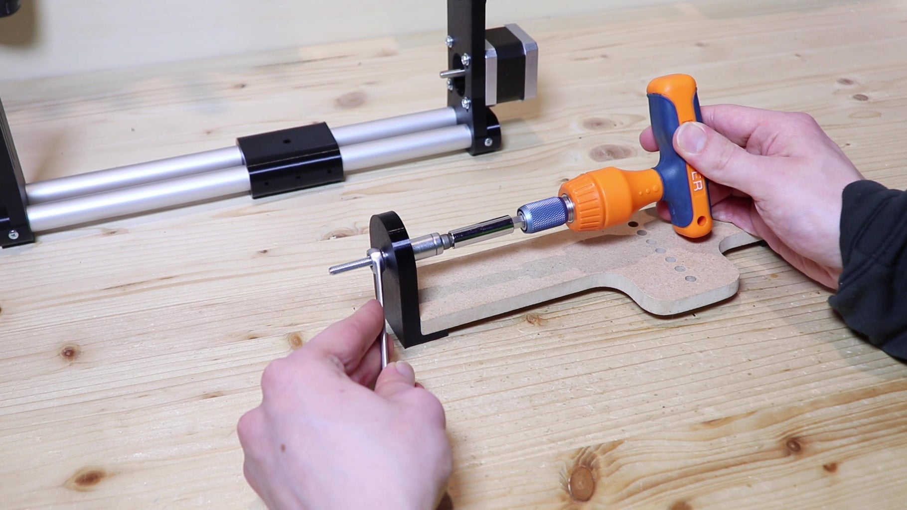
At this point we need something to mount the camera on. So I cut a piece of 9 mm MDF and drilled some holes where the camera will be attached with a ¼ inch screw. I drilled many holes so that I could balance the camera by choosing which hole to attach it to. The shape of the MDF piece doesn't matter, but if you want to make it similar to mine follow the picture above (I have no exact measurements for that part). The I 3D printed the two sides of the camera mount (stl below), and I screwed them to the sides of the MDF piece. Into these two parts I put the two M5 bolts.


Step 3: Assembling the Vertical Movement
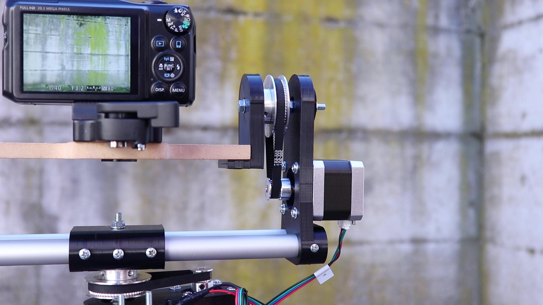

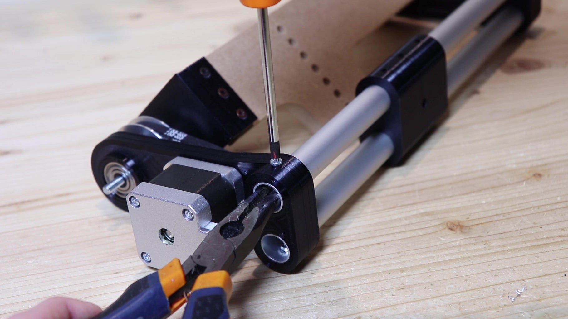
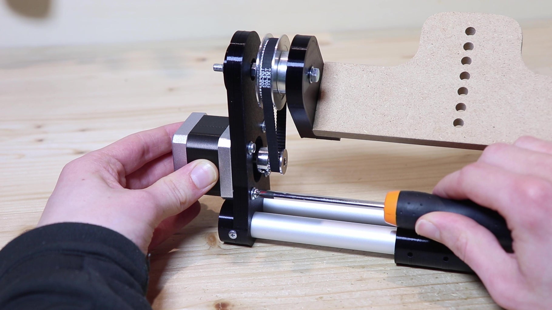
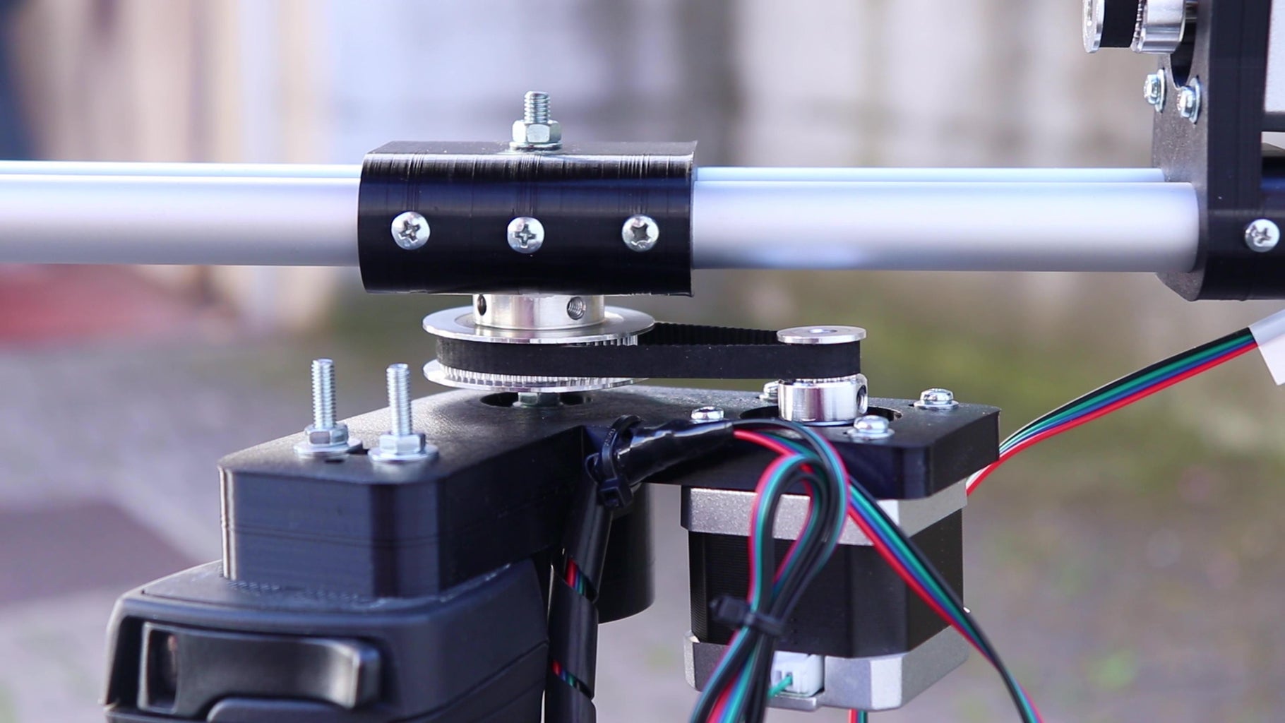
To carry the movement from the motor to the camera I will use two pulleys and a belt. The two pulleys are of different sizes, so as to reduce the speed and increase the force. I took the larger pulley (60 teeth) and inserted it onto one of the two bolts. Before inserting it, I put a piece of double-sided tape on the pulley to increase the friction between the metal and the 3D printed piece. After the pulley I put some nuts, a washer and a small 3D printed adapter, which allows to thread the 5 mm threaded rod into ball bearings with a larger hole, like the ones I had. I also put the same adapter on the other side and put the center piece between the two sides, although I had to disassemble the two sides again to do that. I was forgetting to put the belt in the pulley before reassembling everything. Then I put the smaller pulley (20 teeth) on the motor axis. To tension the belt, I made grooves so that the motor could be pushed down by loosening the screws. I did a test with the electronics that and the vertical movement seemed to work. However getting to this point was not easy, and I had to make two versions of the whole piece.

Step 4: Tripod Mount
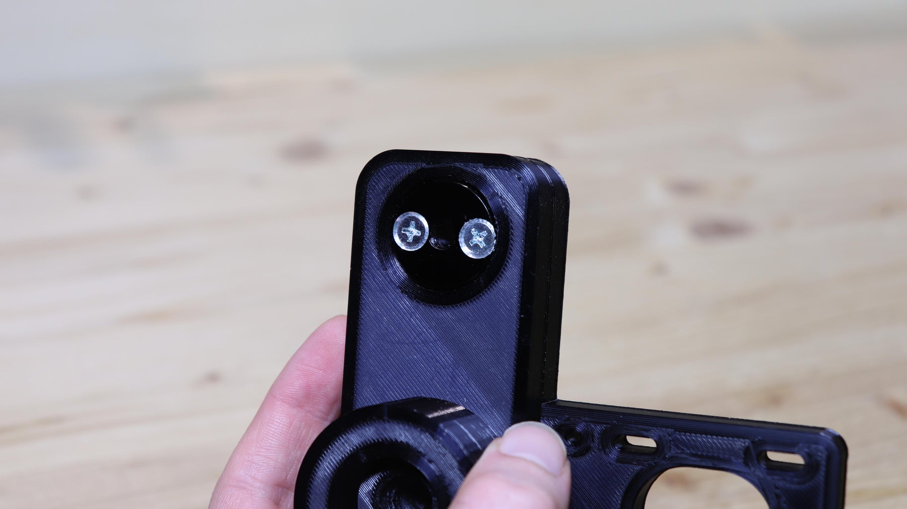

Now we can move on to the horizontal movement, which is actually very similar to the vertical movement, but it is turned of 90 degrees. For this part I printed another part, for which you will find the stl below. This piece will also be used to mount the robot on a tripod, that has an ¼ inch thread on top. So I took a nut with the ¼ inch thread that I recycled from some other photo equipment, and drilled two holes in the edges with a drill press. With these holes, I attached the nut to the 3D printed piece with two countersunk bolts. Washers on the other side are important, since we will need to tighten the bolts quite a bit to make the robot as stable ad possible.
Camera robot horizontal movement

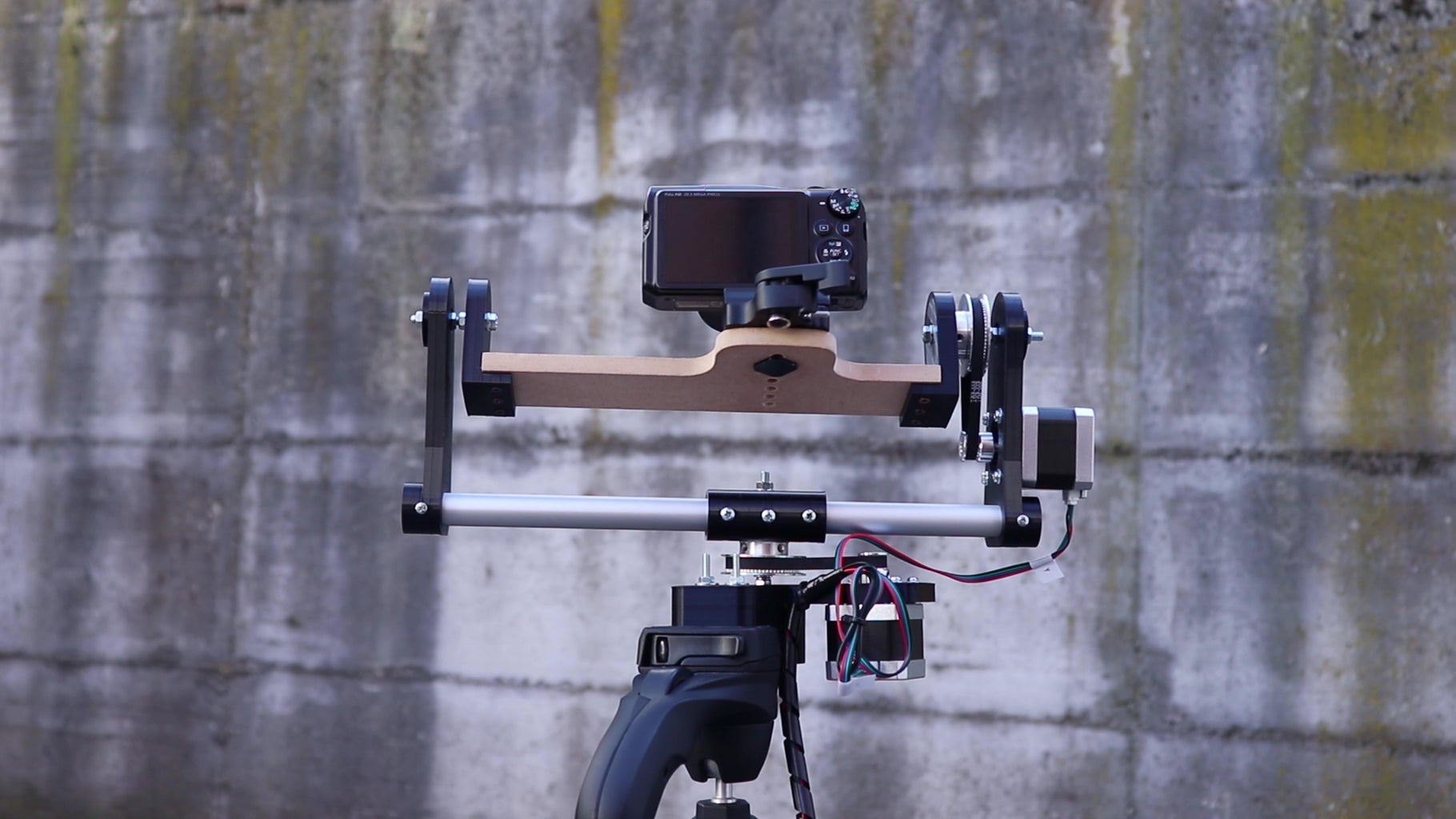
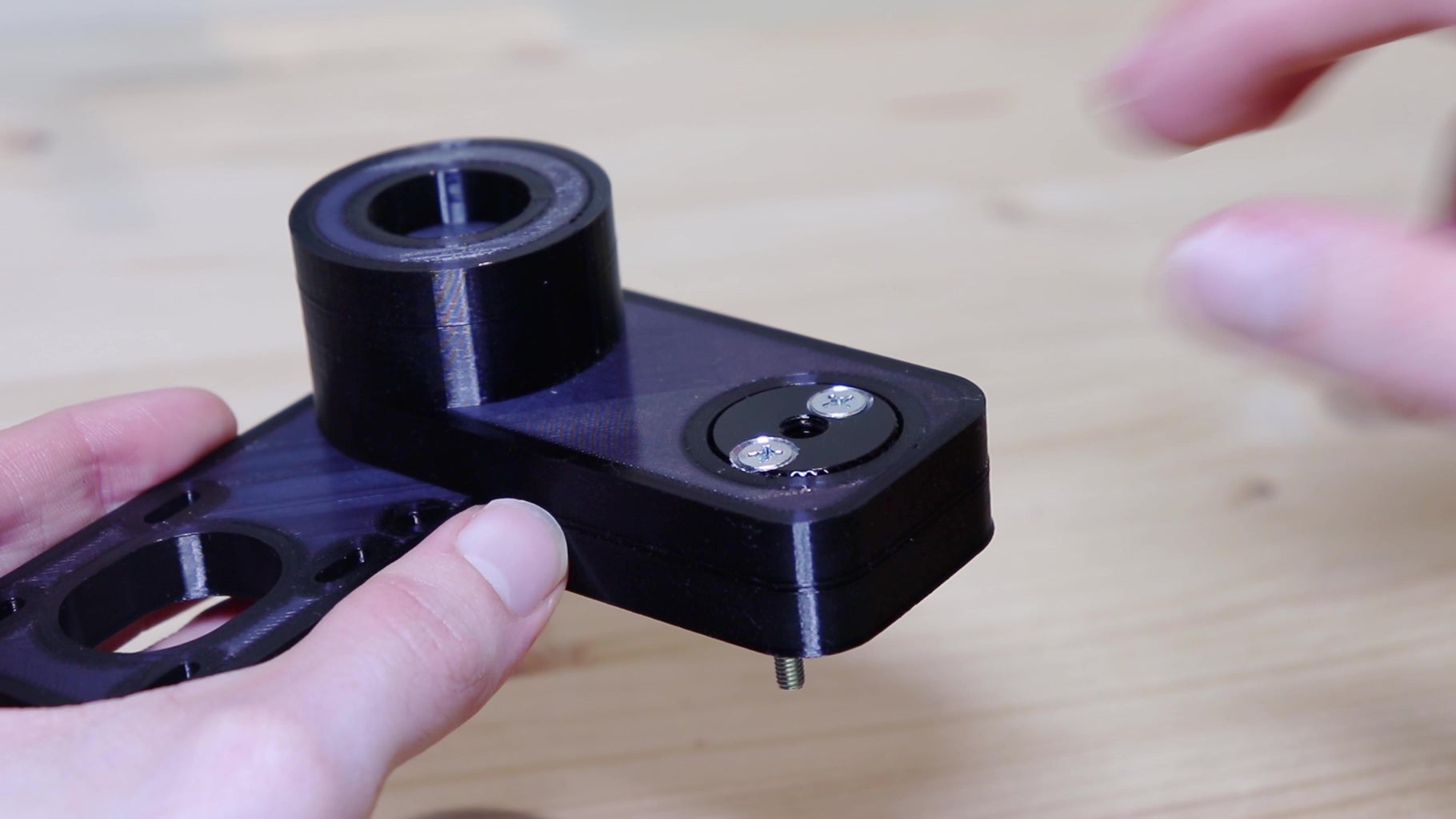
Step 5: Horizontal Movement
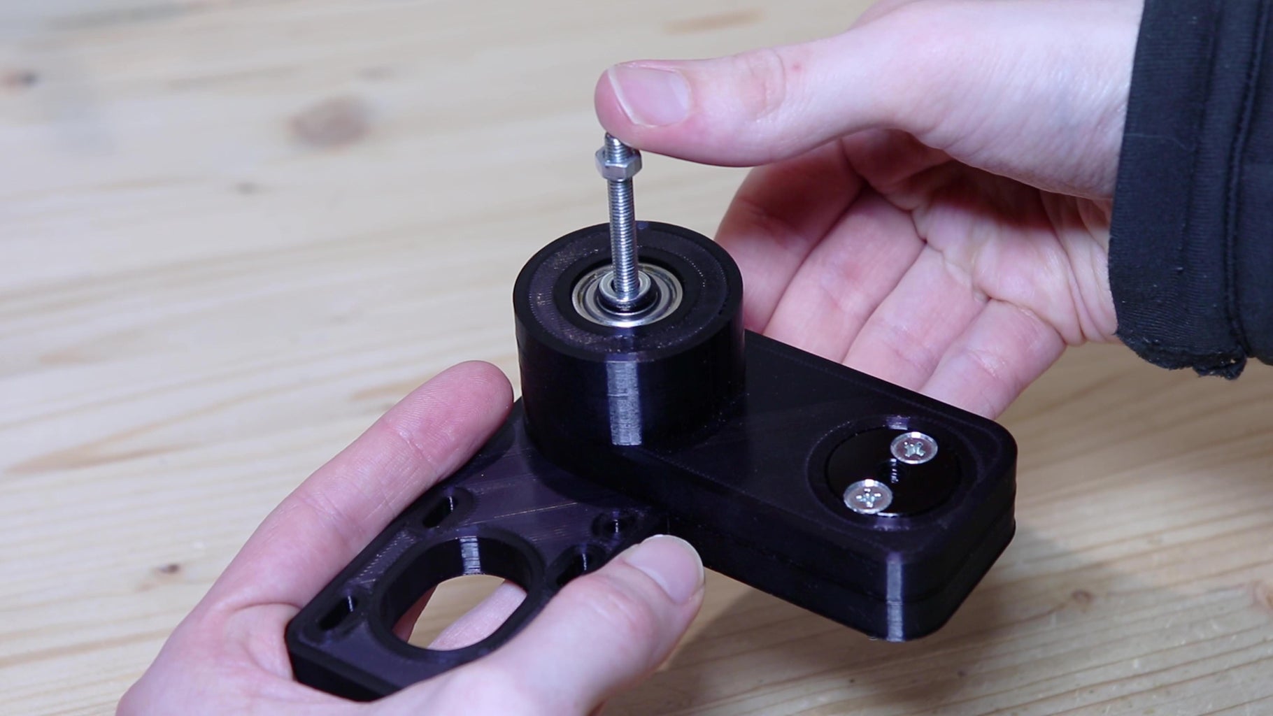
Now that we have made the tripod mount, we can make the actual horizontal movement. In the part we have printed I put two bearings, one on top and one underneath. I cut a piece of around 11 cm of threaded rod, and to fit it into the bearings with as little clearance as possible, I printed two more adapters. To insert the adapters I needed a bit of force, but this ensures that they don't move. I attached the threaded rod to the bearings with two self-locking nuts without over-tightening them, so as not to damage the bearings. I know that this is not the best solution, but I couldn't find any better way of attaching the threaded rod to the bearings. If you have something to suggest, write it in the comments.
I mounted the motor with four M3 bolts to the 3D printed part. Again, I mounted the large pulley on the threaded rod and the small pulley on the motor. I aligned the center piece of the robot with the holes where the camera will be mounted, so that the camera rotates on its axis. Then I attached the center piece to the aluminum tubes with self-tapping screws. I put the whole vertical movement structure on the threaded rod by inserting it into the hole of the center piece, and secured it with a nut.
And so I would say the mechanical part is finished, but to see it in operation we need all the electronics.

Step 6: Stepper Motor Drivers

To move the camera, I used two stepper motors. Stepper motors can make very slow and precise movements, which is why they are used in all 3D printers. Stepper motors, however, cannot be powered directly like regular motors, but need a driver, that is a circuit that energizes the coils in the right order to make the motor move as desired. The driver is connected to an Arduino with two wires, step and dir, that control the direction and when the motor makes a step. By controlling the motors in this way we can precisely determine how much each motor should move. The drivers I used are the TMC2208, which compared to others make the motors completely silent.
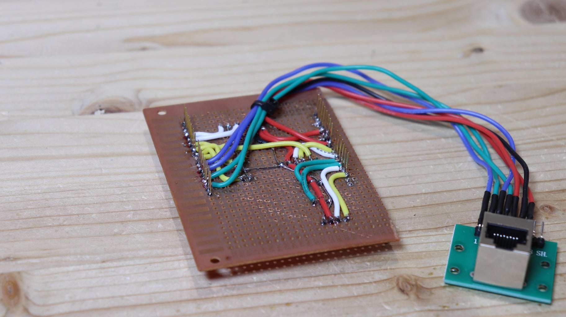
Step 7: Electronics Box
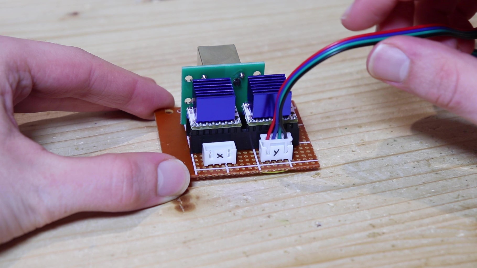

The drivers will be mounted directly on the robot, and will be connected with the eight wires of an Ethernet cable to the Arduino that will be put into the remote control.
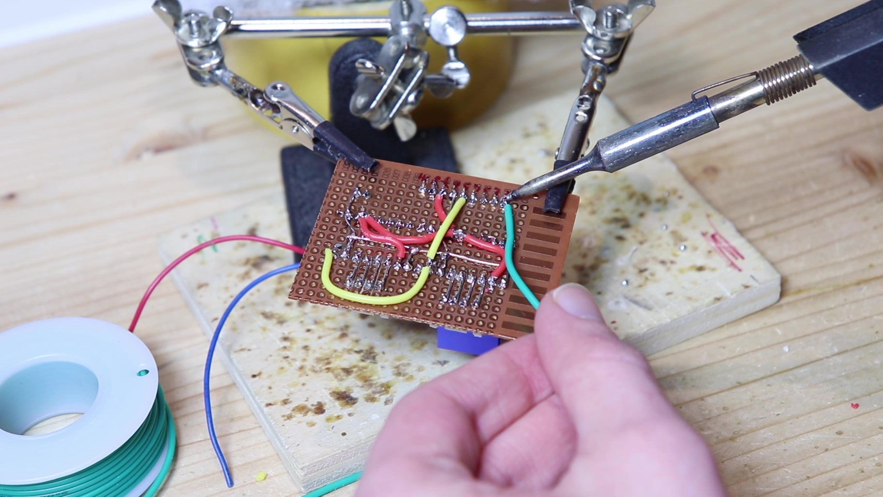
I soldered on a piece of perfboard a RJ45 socket to connect the remote control, connectors to mount the drivers, and JST connectors for the motors. On the 12v supply of each driver I put a capacitor. Then I made all the connections under the perfboard using wires with silicone sheathing, which does not melt with the heat of the soldering iron. To make the connections I followed the schematic that you find in the PDF file in the step below (step 8).
Then we need to adjust max current for the motor on each driver. My drivers have the potentiometer below, so I had to connect the drivers temporarily to the board using jumper wires. Then i connected my multimeter between ground and the little hole (near the potentiometer) nearest to the enable (EN) pin. I rotated the potentiometer with a small screwdriver while measuring the voltage, until I saw around 1v. According to the formula Current limit = Vref x 0.71, this should equal to around 0,710 A. Since my motors have a maximum current of 1,5 A, the current I set should avoid the motors (and also the drivers) from heating too much.
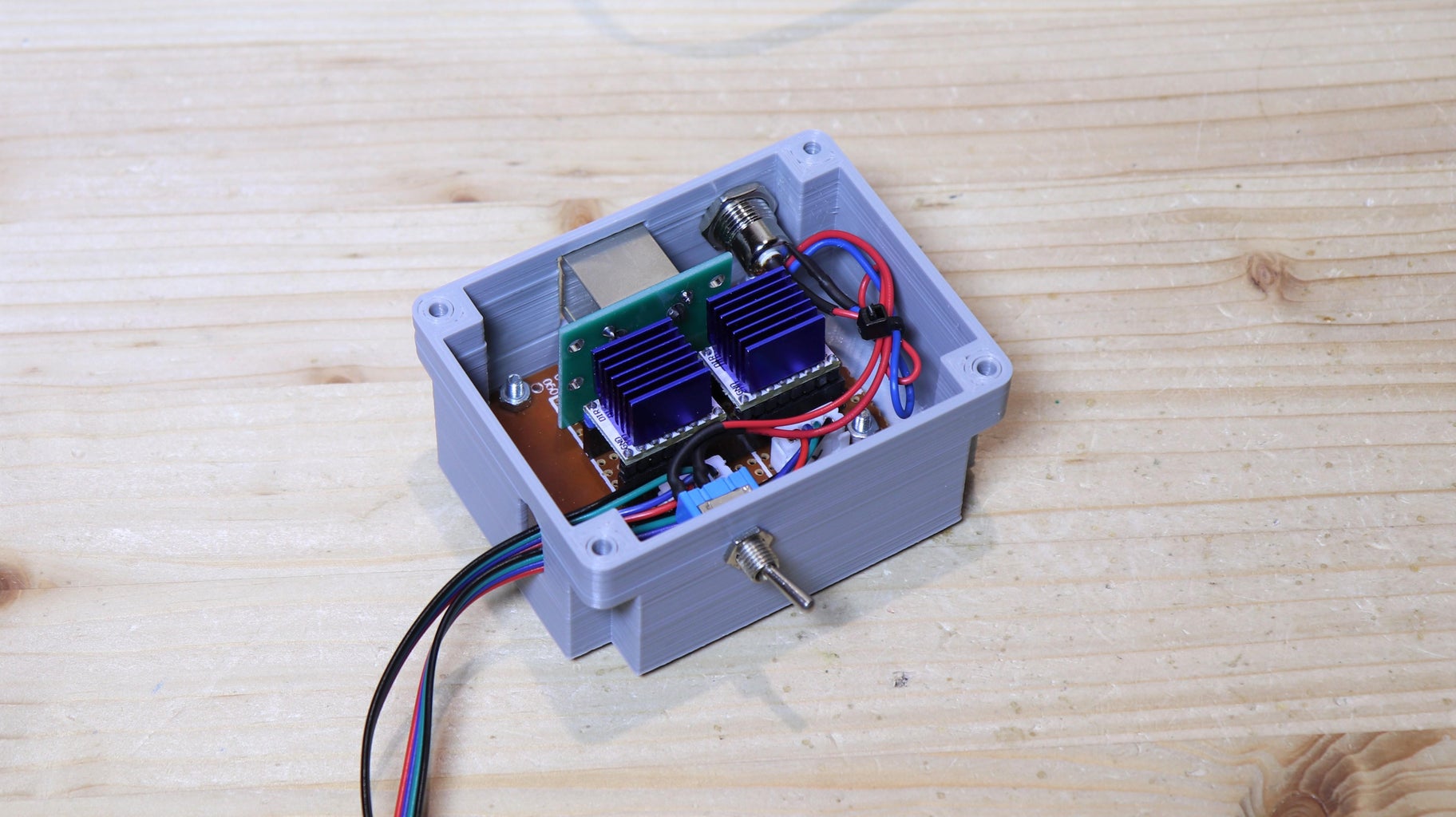
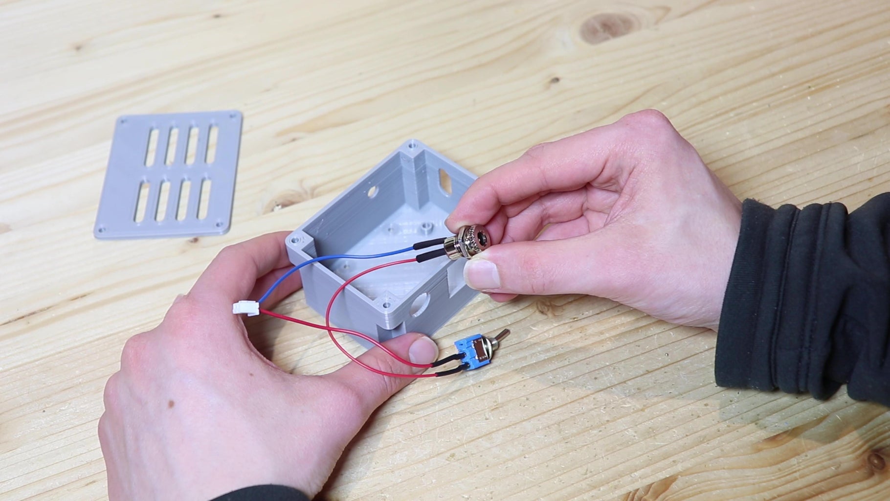
To mount the board, I 3D printed a box with a hole for the RJ45 port. I also connected a 12v power connector and a switch to the JST connector for power.
I connected the cables for the two motors to the JST connectors, and closed the box with its lid and four M3 bolts.
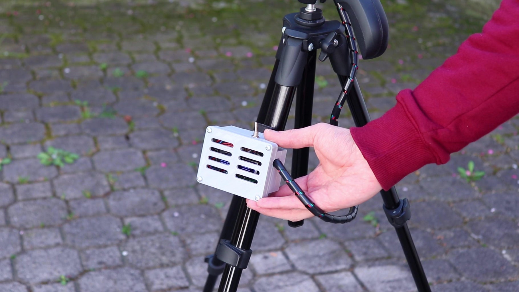
To mount the electronics box on the camera tripod, I 3D printed a super simple slide mechanism, with a part that's mounted on the tripod and a part that's on the box.
Attachments


Step 8: Remote Control
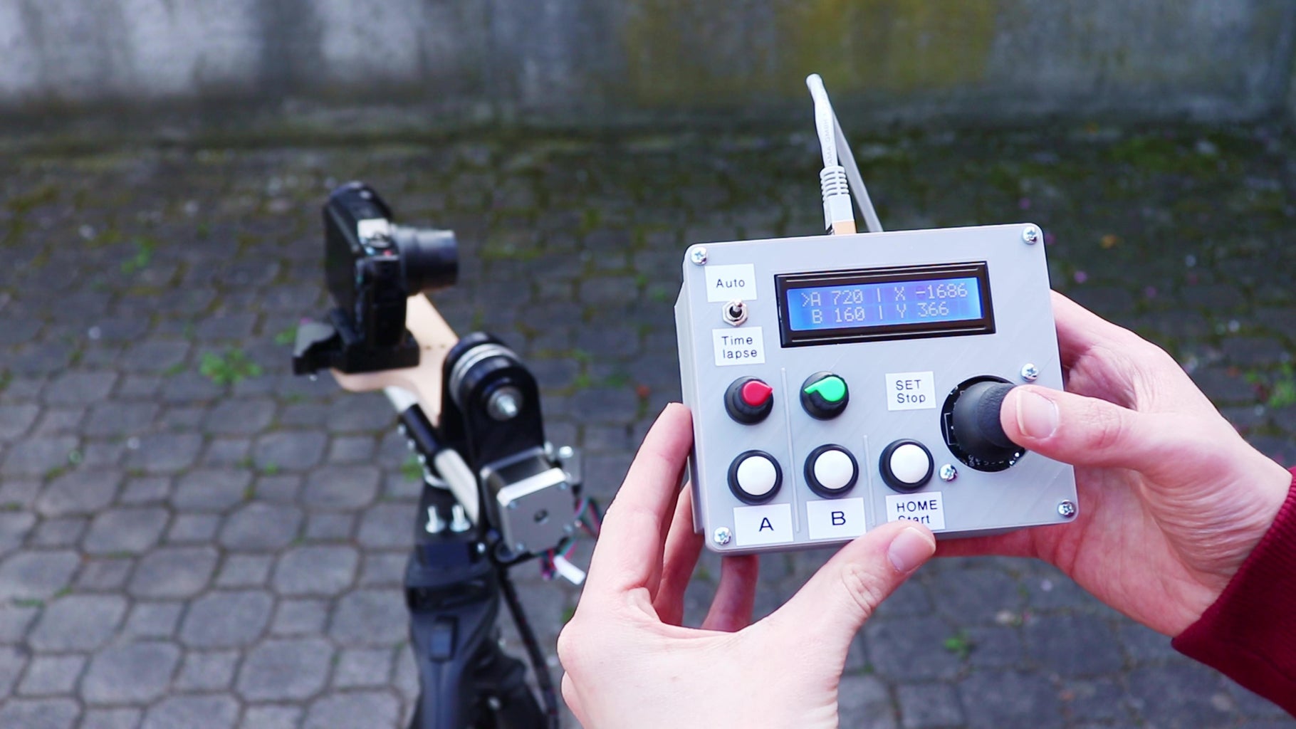
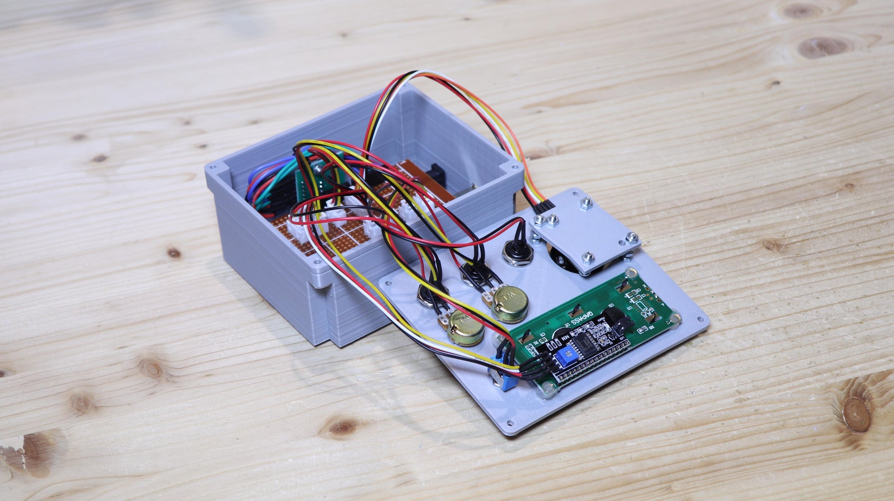
Now we can move on to the remote control with which we can control the movements of the camera. On the remote control there are three buttons, two potentiometers, a joystick and an lcd display with i2c interface.
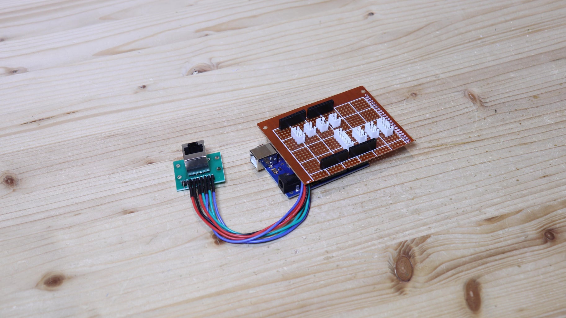
In the remote control I also put an Arduino UNO, to control the motors based on the input from the controls. With another piece of perfboard I created a shield for the Arduino UNO with JST connectors on top to connect the various buttons, potentiometers, ecc... As always the schematics is in the PDF below. However, the JST connectors are connected to different pins on the Arduino. Of course to the various components that will be on the remote control panel I soldered wires with the JST connectors. JST connectors aren't necessary, and you can avoid them, but they made the assembly a lot easier. I also connected the RJ45 port to the pins of the Arduino. With the RJ45 cable, the Arduino will get 12 power from the robot, and will control the motor drivers with two wires for each motor.
The structure of the remote control is also 3D printed. Inside the box I mounted the Arduino and the Ethernet jack to which the electronics that are on the robot will be connected. The remote control panel has holes in which to mount the buttons and potentiometers. On the panel I also put the switch to choose the three modes of operation: live, auto and timelapse. To mount the joystick, I made a 3D printed bracket, but I don't like it at all, so I think I will make a better one soon. As a last thing, I glued the LCD display with hot glue. I closed the remote control with four M3 screws and we are done.
Attachments


Step 9: Arduino Code
At this point I wrote the code for the Arduino, and after writing 600 lines of code and solving around a million problems everything seems to work. I uploaded the code to the Arduino before connecting anything to it. To make the stepper motors work, you will need to install the AccelStepper and MultiStepper libraries on the Arduino IDE, and the LiquidCrystal i2c library for the display.
#include <AccelStepper.h>
#include <MultiStepper.h>
#include <LiquidCrystal_I2C.h>


// Define the stepper motor and the pins that is connected to
AccelStepper stepper1(1, 2, 5); // (Type of driver: with 2 pins, STEP, DIR)
AccelStepper stepper2(1, 3, 6);


MultiStepper steppers;


LiquidCrystal_I2C lcd(0x27, 16, 2);


int xpin = A0;
int ypin = A1;
int v1pin = A2;
int v2pin = A3;


int homepin = 10;
int Apin = 9;
int Bpin = 8;
int SETpin = 7;
int timelapseMode = 11;
int autoMode = 12;


const int longPress = 600;


int v1;
int v2;
int v;
bool vSET; //true: v1 - false: v2
bool isMoving = true;
bool page = true;


int mode; //1: live - 2: auto - 3: timelapse


int xA;
int xB;
int yA;
int yB;


long timeBetweenPhotos;
long totalPhotos;
long photosTaken;
int xStep;
int yStep;


long gotoposition[2];


void setup() {
  pinMode(homepin, INPUT_PULLUP);
  pinMode(Apin, INPUT_PULLUP);
  pinMode(Bpin, INPUT_PULLUP);
  pinMode(SETpin, INPUT_PULLUP);
  pinMode(timelapseMode, INPUT_PULLUP);
  pinMode(autoMode, INPUT_PULLUP);

  // Set maximum speed value for the stepper
  stepper1.setMaxSpeed(1000);
  stepper1.setAcceleration(1000);
  stepper1.setCurrentPosition(0);


  stepper2.setMaxSpeed(1000);
  stepper2.setAcceleration(1000);
  stepper2.setCurrentPosition(0);


  steppers.addStepper(stepper1);
  steppers.addStepper(stepper2);


  lcd.init();
  lcd.backlight();
  lcd.setCursor(2, 0);
  lcd.print("Camera Robot");
  delay(1000);
  lcd.clear();
}


void loop() {

//// LIVE mode ///////////////////////////////////////////////////////////////////////////
  if(digitalRead(timelapseMode) == 1 && digitalRead(autoMode) == 1) {
    if(mode != 1) {
      delay(500);
      if(digitalRead(timelapseMode) == 1 && digitalRead(autoMode) == 1) {
      mode = 1;
      isMoving = true;
      lcd.clear();
      lcd.setCursor(2,0);
      lcd.print("-LIVE MODE-");
      delay(1000);
      lcd.clear();
      }
    }

    v1 = map(analogRead(v1pin), 0, 1023, 0, 99)*10;
    v2 = map(analogRead(v2pin), 0, 1023, 0, 99)*10;

    //select speed with A and B buttons
    if(digitalRead(Apin) == 0) {
      vSET = true;

      lcd.setCursor(0,0);
      lcd.print(">");
      lcd.setCursor(0,1);
      lcd.print(" ");
    }
    if(digitalRead(Bpin) == 0) {
      vSET = false;

      lcd.setCursor(0,0);
      lcd.print(" ");
      lcd.setCursor(0,1);
      lcd.print(">");

    }
    if(vSET == true) {
      v = v1;
    }
    if(vSET == false) {
      v = v2;
    }


    //home motors with button
    if(digitalRead(homepin) == 0 && !digitalRead(SETpin) == 0 && (stepper1.currentPosition() != 0 || stepper2.currentPosition() != 0) ) {
      lcd.clear();
      lcd.setCursor(0,0);
      lcd.print("Going to HOME...");
      lcd.setCursor(0,1);
      lcd.print("X 0");
      lcd.setCursor(9,1);
      lcd.print("Y 0");

      isMoving = true;
      stepper2.setMaxSpeed(v);
      stepper1.setMaxSpeed(v);
      gotoposition[0] = 0;
      gotoposition[1] = 0;
      steppers.moveTo(gotoposition);
      steppers.run();
      while(steppers.run() == true && digitalRead(SETpin) == 1) {
        steppers.run();
      }
      stepper2.setMaxSpeed(1000);
      stepper1.setMaxSpeed(1000);
    }

    //set new home position
    if(digitalRead(homepin) == 0 && digitalRead(SETpin) == 0) {
      isMoving = true;
      stepper2.setCurrentPosition(0);
      stepper1.setCurrentPosition(0);
      delay(longPress);
    }

    //move camera using the joystick
    if(analogRead(xpin) > 600){
      stepper1.setSpeed(map(analogRead(xpin), 600, 1023, 0, v));
      stepper1.runSpeed();
      isMoving = true;
    }

    if(analogRead(xpin) < 400){
      stepper1.setSpeed(map(analogRead(xpin), 400, 0, 0, -v));
      stepper1.runSpeed();
      isMoving = true;
    }

    if(analogRead(ypin) > 600){
      stepper2.setSpeed(map(analogRead(ypin), 600, 1023, 0, v));
      stepper2.runSpeed();
      isMoving = true;
    }

    if(analogRead(ypin) < 400){
      stepper2.setSpeed(map(analogRead(ypin), 400, 0, 0, -v));
      stepper2.runSpeed();
      isMoving = true;
    }


    //update display only when the motors are stopped, to avoid overloading the Arduino
    if(analogRead(xpin) > 400 && analogRead(xpin) < 600 && analogRead(ypin) > 400 && analogRead(ypin) < 600) {
      stepper1.setSpeed(0);
      stepper2.setSpeed(0);

      lcd.setCursor(1,0);
      lcd.print("A");
      lcd.setCursor(3,0);
      lcd.print(v1);
      lcd.setCursor(1,1);
      lcd.print("B");
      lcd.setCursor(3,3);
      lcd.print(v2);
      lcd.setCursor(7,0);
      lcd.print("|");
      lcd.setCursor(7,1);
      lcd.print("|");
      if(v1 < 100) {
        lcd.setCursor(5,0);
        lcd.print(" ");
      }
      if(v2 < 100) {
        lcd.setCursor(5,1);
        lcd.print(" ");
      }
      if(vSET == true) {
        lcd.setCursor(0,0);
        lcd.print(">");
        lcd.setCursor(0,1);
        lcd.print(" ");
      }
      if(vSET == false) {
        lcd.setCursor(0,0);
        lcd.print(" ");
        lcd.setCursor(0,1);
        lcd.print(">");
      }
      if(isMoving == true) {
        lcd.clear();
        lcd.setCursor(9,0);
        lcd.print("X");
        lcd.setCursor(11,0);
        lcd.print(stepper1.currentPosition());

        lcd.setCursor(9,1);
        lcd.print("Y");
        lcd.setCursor(11,1);
        lcd.print(stepper2.currentPosition());


        isMoving = false;
      }
    }
  }


//// AUTO mode ///////////////////////////////////////////////////////////////////////////
  if(digitalRead(timelapseMode) == 1 && digitalRead(autoMode) == 0) {
    if(mode != 2) {
      mode = 2;
      xA = 0;
      xB = 0;
      yA = 0;
      yB = 0;
      isMoving = true;
      lcd.clear();
      lcd.setCursor(2,0);
      lcd.print("-AUTO MODE-");
      lcd.setCursor(0,1);
      lcd.print("Set speed: A");
      delay(2000);
      lcd.clear();
    }

    v1 = map(analogRead(v1pin), 0, 1023, 0, 99)*10;
    v2 = map(analogRead(v2pin), 0, 1023, 0, 99)*100;


    //move camera using the joystick
    if(analogRead(xpin) > 600){
      stepper1.setSpeed(map(analogRead(xpin), 600, 1023, 0, v2));
      stepper1.runSpeed();
      isMoving = true;
    }

    if(analogRead(xpin) < 400){
      stepper1.setSpeed(map(analogRead(xpin), 400, 0, 0, -v2));
      stepper1.runSpeed();
      isMoving = true;
    }

    if(analogRead(ypin) > 600){
      stepper2.setSpeed(map(analogRead(ypin), 600, 1023, 0, v2));
      stepper2.runSpeed();
      isMoving = true;
    }

    if(analogRead(ypin) < 400){
      stepper2.setSpeed(map(analogRead(ypin), 400, 0, 0, -v2));
      stepper2.runSpeed();
      isMoving = true;
    }


    //set A and B positions
    if(digitalRead(Apin) == 0 && digitalRead(SETpin) == 0) {
      xA = stepper1.currentPosition();
      yA = stepper2.currentPosition();
      isMoving = true;
      delay(longPress);
    }


    if(digitalRead(Bpin) == 0 && digitalRead(SETpin) == 0) {
      xB = stepper1.currentPosition();
      yB = stepper2.currentPosition();
      isMoving = true;
      delay(longPress);
    }


    //go to A and B positions
    if(digitalRead(Apin) == 0 && digitalRead(SETpin) == 1 && (stepper1.currentPosition() != xA || stepper2.currentPosition() != yA)) {
      lcd.clear();
      lcd.setCursor(0,0);
      lcd.print("Going to A...");
      lcd.setCursor(0,1);
      lcd.print("X");
      lcd.setCursor(2,1);
      lcd.print(xA);
      lcd.setCursor(9,1);
      lcd.print("Y");
      lcd.setCursor(11,1);
      lcd.print(yA);

      gotoposition[0] = xA;
      gotoposition[1] = yA;
      stepper1.setMaxSpeed(v1);
      stepper2.setMaxSpeed(v1);
      steppers.moveTo(gotoposition);
      while(steppers.run() == true && digitalRead(homepin) == 1 && digitalRead(SETpin) == 1) {
        steppers.run();
      }
      stepper1.setMaxSpeed(1000);
      stepper2.setMaxSpeed(1000);
      isMoving = true;
    }


    if(digitalRead(Bpin) == 0 && digitalRead(SETpin) == 1 && (stepper1.currentPosition() != xB || stepper2.currentPosition() != yB)) {
      lcd.clear();
      lcd.setCursor(0,0);
      lcd.print("Going to B...");
      lcd.setCursor(0,1);
      lcd.print("X");
      lcd.setCursor(2,1);
      lcd.print(xB);
      lcd.setCursor(9,1);
      lcd.print("Y");
      lcd.setCursor(11,1);
      lcd.print(yB);

      gotoposition[0] = xB;
      gotoposition[1] = yB;
      stepper1.setMaxSpeed(v1);
      stepper2.setMaxSpeed(v1);
      steppers.moveTo(gotoposition);
      steppers.run();
      while(steppers.run() == true && digitalRead(homepin) == 1 && digitalRead(SETpin) == 1) {
        steppers.run();
      }
      stepper1.setMaxSpeed(1000);
      stepper2.setMaxSpeed(1000);
      isMoving = true;
    }

    //update display only when the motors are stopped, to avoid overloading the Arduino
    if(analogRead(xpin) > 400 && analogRead(xpin) < 600 && analogRead(ypin) > 400 && analogRead(ypin) < 600) {
      stepper1.setSpeed(0);
      stepper2.setSpeed(0);


      lcd.setCursor(0,0);
      lcd.print("VEL");
      lcd.setCursor(0,1);
      lcd.print(v1);
      if(v1 < 100) {
        lcd.setCursor(2,1);
        lcd.print(" ");
      }
      if(isMoving == true) {
        lcd.clear();
        lcd.setCursor(4,0);
        lcd.print("X");
        lcd.setCursor(5,0);
        lcd.print(xA);

        lcd.setCursor(10,0);
        lcd.print(">");
        lcd.setCursor(11,0);
        lcd.print(xB);

        lcd.setCursor(4,1);
        lcd.print("Y");
        lcd.setCursor(5,1);
        lcd.print(yA);

        lcd.setCursor(10,1);
        lcd.print(">");
        lcd.setCursor(11,1);
        lcd.print(yB);


        isMoving = false;
      }
    }
  }


//// TIME-LAPSE mode ///////////////////////////////////////////////////////////////////////////
  if(digitalRead(timelapseMode) == 0 && digitalRead(autoMode) == 1) {
    if(mode != 3) {
      mode = 3;
      xA = 0;
      xB = 0;
      yA = 0;
      yB = 0;
      isMoving = true;
      lcd.clear();
      lcd.setCursor(0,0);
      lcd.print("TIME-LAPSE MODE");
      lcd.setCursor(0,1);
      lcd.print("Time: A - NR: B");
      delay(2000);
      lcd.clear();
    }

    timeBetweenPhotos = map(analogRead(v1pin), 0, 1023, 0, 20000)/200;
    totalPhotos = map(analogRead(v2pin), 0, 1023, 0, 99)*10;


    //move camera using the joystick
    if(analogRead(xpin) > 600){
      stepper1.setSpeed(300);
      stepper1.runSpeed();
    }

    if(analogRead(xpin) < 400){
      stepper1.setSpeed(-300);
      stepper1.runSpeed();
    }

    if(analogRead(ypin) > 600){
      stepper2.setSpeed(300);
      stepper2.runSpeed();
    }

    if(analogRead(ypin) < 400){
      stepper2.setSpeed(-300);
      stepper2.runSpeed();
    }


    //set A and B positions
    if(digitalRead(Apin) == 0) {
      xA = stepper1.currentPosition();
      yA = stepper2.currentPosition();
      delay(longPress);
    }


    if(digitalRead(Bpin) == 0) {
      xB = stepper1.currentPosition();
      yB = stepper2.currentPosition();
      delay(longPress);
    }


    //calculate how much the motors should move for each photo that is taken
    xStep = (xB - xA)/totalPhotos;
    yStep = (yB - yA)/totalPhotos;

    //start timelapse
    if(digitalRead(homepin) == 0 && digitalRead(SETpin) == 1) {
      photosTaken = 0;

      //go to start (A) position
      bool goneToA = false;
      gotoposition[0] = xA;
      gotoposition[1] = yA;
      stepper1.setMaxSpeed(200);
      stepper2.setMaxSpeed(200);
      steppers.moveTo(gotoposition);
      if(stepper1.currentPosition() == xA && stepper2.currentPosition() == yA) {
        goneToA = true;
      }
      steppers.run();
      if(goneToA == false) {
        stepper1.setMaxSpeed(200);
        stepper2.setMaxSpeed(200);
        lcd.clear();
        lcd.setCursor(0,0);
        lcd.print("Going to A...");
        lcd.setCursor(0,1);
        lcd.print("X");
        lcd.setCursor(2,1);
        lcd.print(xA);
        lcd.setCursor(9,1);
        lcd.print("Y");
        lcd.setCursor(11,1);
        lcd.print(yA);
        while(steppers.run() == true && digitalRead(SETpin) == 1) {
          steppers.run();
          goneToA = true;
        }
      }

      //do timelapse
      while(digitalRead(SETpin) == 1 && photosTaken < totalPhotos) {
        gotoposition[0] = stepper1.currentPosition() + xStep;
        gotoposition[1] = stepper2.currentPosition() + yStep;


        stepper1.setMaxSpeed(50);
        stepper2.setMaxSpeed(50);

        steppers.moveTo(gotoposition);
        steppers.run();
        while(steppers.run() == true && digitalRead(SETpin) == 1) {
          steppers.run();
        }
        photosTaken++;

        lcd.clear();
        lcd.setCursor(0,0);
        lcd.print("Remain:");
        lcd.setCursor(8,0);
        lcd.print(timeBetweenPhotos*(totalPhotos - photosTaken)/60);
        lcd.setCursor(12,0);
        lcd.print("min");
        lcd.setCursor(7,1);
        lcd.print(totalPhotos - photosTaken);
        lcd.setCursor(11,1);
        lcd.print("photo");

        while(digitalRead(SETpin) == 1 && !(millis() % (timeBetweenPhotos*1000)) == 0) {}

      }
      stepper1.setMaxSpeed(1000);
      stepper2.setMaxSpeed(1000);
      lcd.clear();
    }

    //update display only when the motors are stopped, to avoid overloading the Arduino
    if(analogRead(xpin) > 400 && analogRead(xpin) < 600 && analogRead(ypin) > 400 && analogRead(ypin) < 600) {
      stepper1.setSpeed(0);
      stepper2.setSpeed(0);

      //display time between photos and total time
      if(digitalRead(SETpin) == 1) {
        if(page == false) {
          lcd.clear();
          page = true;
        }
        //lcd.setCursor(0,0);
        //lcd.print("Time");
        lcd.setCursor(0,0);
        lcd.print(timeBetweenPhotos);
        lcd.setCursor(3,0);
        lcd.print("s");
        if(timeBetweenPhotos < 100) {
          lcd.setCursor(2,0);
          lcd.print(" ");
        }
        if(timeBetweenPhotos < 10) {
          lcd.setCursor(1,0);
          lcd.print(" ");
        }

        lcd.setCursor(0,1);
        lcd.print("Total");
        lcd.setCursor(6,1);
        lcd.print((timeBetweenPhotos*totalPhotos)/60);
        lcd.setCursor(10,1);
        lcd.print("min");
        if(((timeBetweenPhotos*totalPhotos)/60) < 1000) {
          lcd.setCursor(9,1);
          lcd.print(" ");
        }
        if(((timeBetweenPhotos*totalPhotos)/60) < 100) {
          lcd.setCursor(8,1);
          lcd.print(" ");
        }
        if(((timeBetweenPhotos*totalPhotos)/60) < 10) {
          lcd.setCursor(7,1);
          lcd.print(" ");
        }
        //display total photos
        lcd.setCursor(6,0);
        lcd.print(totalPhotos);
        lcd.setCursor(10,0);
        lcd.print("photos");
        if(totalPhotos < 100) {
          lcd.setCursor(8,0);
          lcd.print(" ");
        }
      }


      //display A and B positions when SET is pressed
      if(digitalRead(SETpin) == 0) {
        if(page == true) {
          lcd.clear();
          page = false;
        }
        lcd.setCursor(0,0);
        lcd.print("X");
        lcd.setCursor(2,0);
        lcd.print(xA);

        lcd.setCursor(8,0);
        lcd.print(">");
        lcd.setCursor(10,0);
        lcd.print(xB);

        lcd.setCursor(0,1);
        lcd.print("Y");
        lcd.setCursor(2,1);
        lcd.print(yA);

        lcd.setCursor(8,1);
        lcd.print(">");
        lcd.setCursor(10,1);
        lcd.print(yB);
      }
    }
  }
}
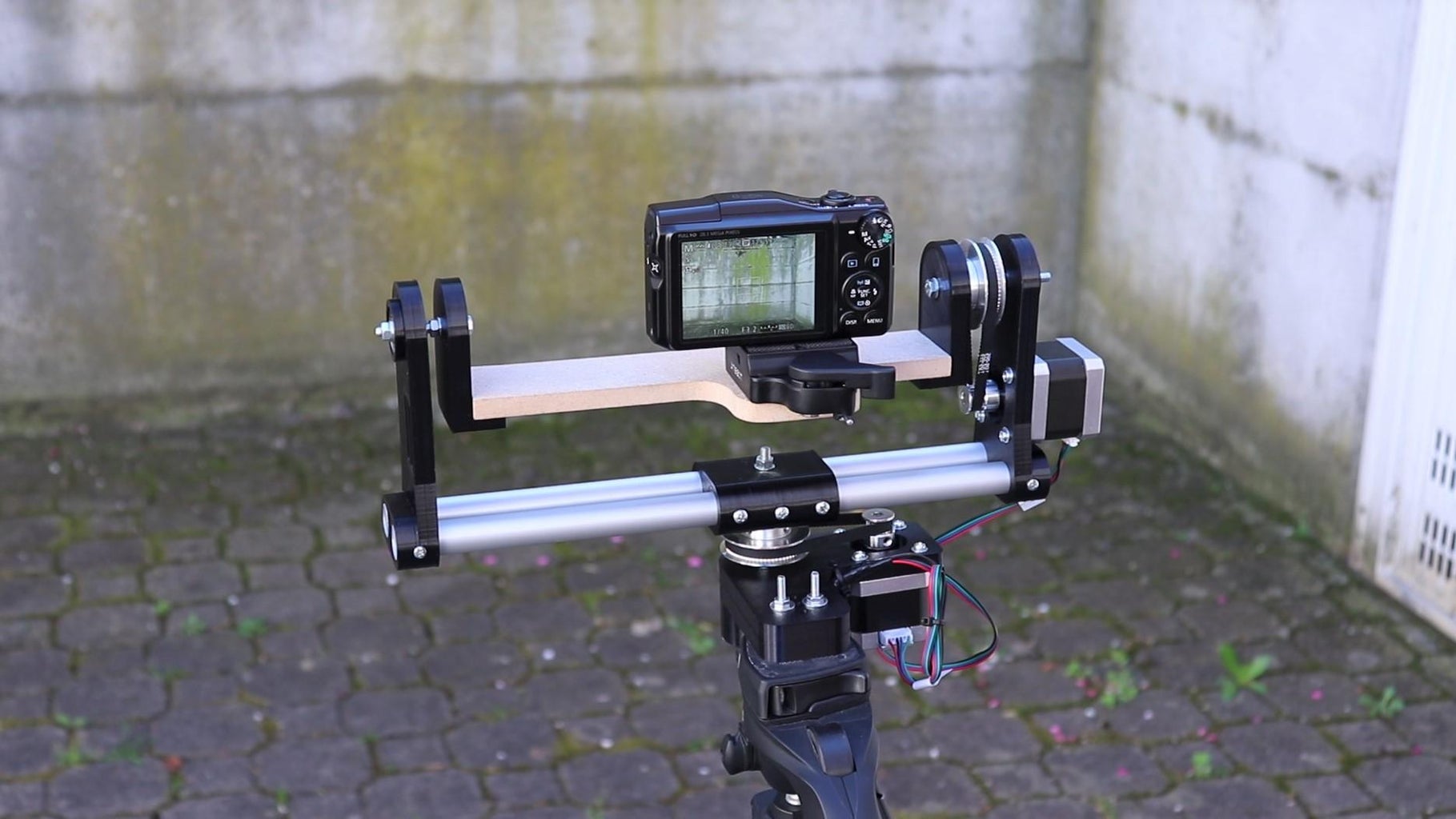
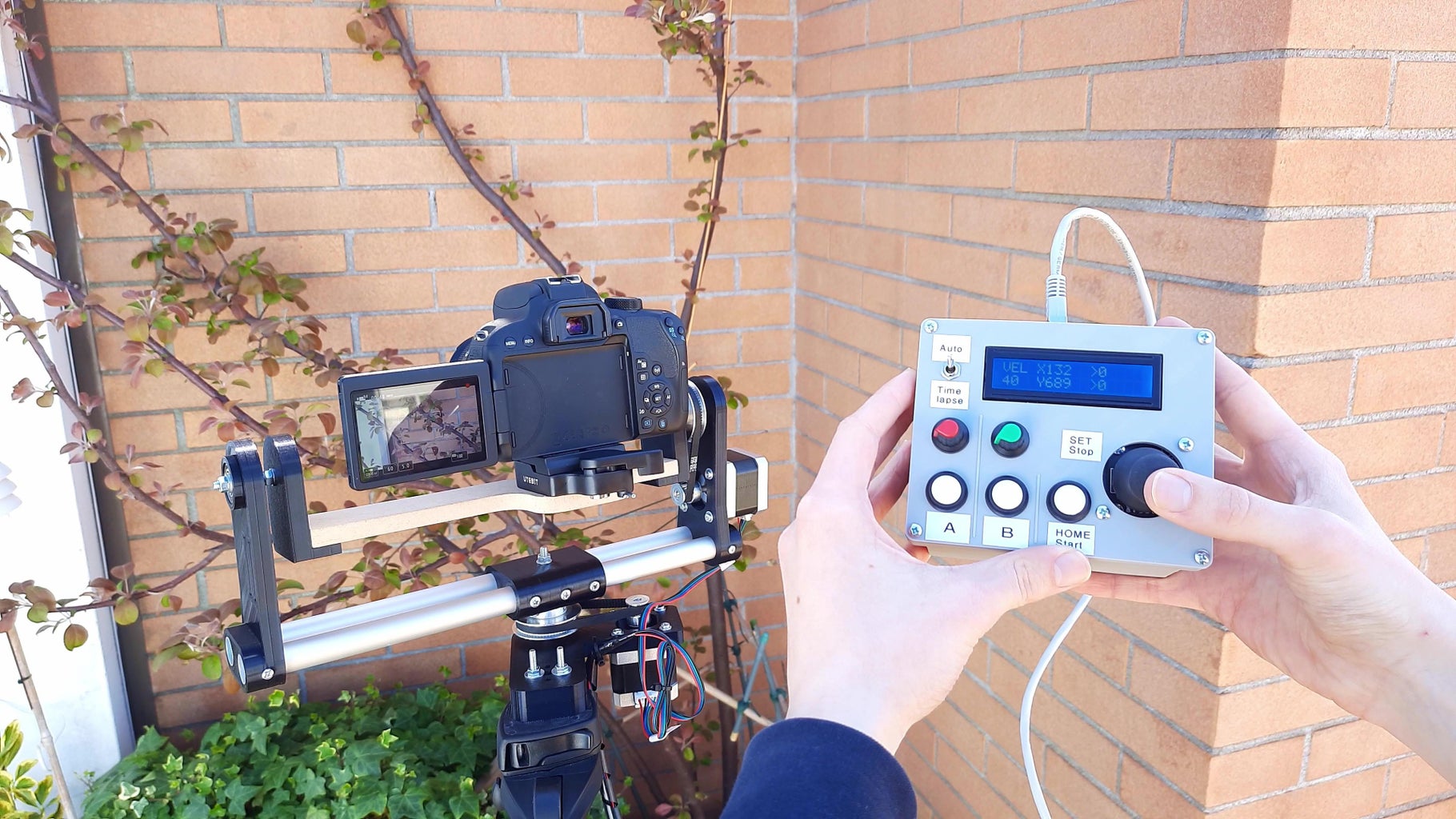
Step 10: Using the Robot!

Finally we have finished building the camera robot, and we can use it. I mounted the robot on the tripod that I usually use for the camera, and on top of the robot I put a quick release to mount the camera. I connected the remote control to the robot with the ethernet cable. To power the robot I used a 12v power supply, but maybe in the future I will add the option to power it with batteries, that could be useful when making outdoor videos. Now that the robot is on we just have to try it out.
The robot has three functioning modes:
- LIVE mode: in this mode the camera is controlled with the joystick
- AUTO mode: in this mode you can save two positions and the motors will move smoothly between them by clicking a button
- Timelapse mode: this mode divides a camera movement into small steps and goes to the next step after every photo of the timelapse is taken, to create an amazing effect once the photos are sped up
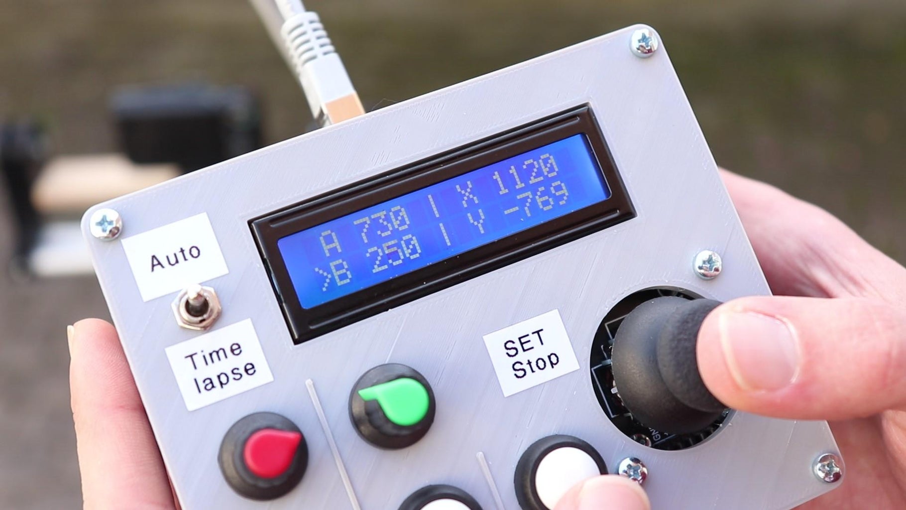
With the toggle switch in the center we are in live mode, meaning we can control the horizontal and vertical movement of the camera with the joystick.
- With the two potentiometers we can set two speeds
- We can choose which speed to use with the A and B buttons
- With the HOME button we can return the camera to position 0
- By pressing the center joystick button and HOME together we set the current position as 0
On the display we see the two speeds, the chosen speed, and the X and Y position of the motors.
By moving the toggle switch to Auto we are in automatic mode.
- With the joystick we can move the camera as in live mode
- With the B potentiometer we can set the speed for the camera movement with the joystick
- With the A potentiometer we can set the speed for the automatic camera movements
- By pressing SET (center button of the joystick) and the A or B buttons, we can save the position we are at
- By pressing A or B we have the camera move between the two positions automatically
On the display we can see the two positions that we have saved and the A speed.
This mode is very useful for taking shots of, for example, an object or a landscape with very smooth and precise movements.
Time-lapse mode is for making time-lapse shots with the camera moving a little bit in each shot, to get a really nice effect.
- With the joystick we can move the camera as in live mode
- By pressing SET (center button of the joystick) and the A button, we can save the position we are at as start position of the timelapse
- By pressing SET (center button of the joystick) and the B button, we can save the position we are at as end position of the timelapse
- With the A potentiometer we can set the time between the photos of the timelapse
- With the B potentiometer we can set the number of photos we want to take
- Of course we have to put the camera in timelapse mode (or use an external intervalometer) and set the same time between photos that we have set on the robot
- The display shows the time between photos, the total photos and the total estimated time in minutes
- By pressing SET we can go to the second page of the display, that shows the start and end position of the timelapse
When everything is set we press the HOME button to start the timelapse. Then the robot will go to the A position and start making a little movement for every photo. When we see the remaining photos and time on the display we can start the timelapse from the camera, and wait for it to finish.
Maybe in the future I will integrate the intervalometer for the camera in the robot itself, as it isn't hard to do.
When doing any of the automated movements (timelapse or auto mode) we can immediately stop the motors by clicking on the SET button (center of the joystick). This is a safety feature that prevents damaging the robot or, worse, the camera.
Step 11: Finished
As you have seen the robot I've built has a lot of functions, and the remote control interface, although it may seem confusing the first time, is done like that to make the robot very fast to use by having all controls always available, without having to scroll trough menus. Of course this is just the first version and there is a lot to improve, like making a PCB instead of the perfboard or design the mechanical part to be more robust. However I hope you enjoyed reading this guide as I enjoyed making this project, and I hope to see you in the next Instructable. If you want to see more details and some videos made with this robot, watch the video on my YouTube channel. Bye!


12 Comments
5 weeks ago
Great!!! Congratulation!
Reply 4 days ago
Well done !
I wish to build this same robot.
Where can I purchase the parts ( stepper motors etc)
Benedict Mogendi
Reply 4 weeks ago
Thanks!
4 weeks ago
Замечательный проект!!!! Я как раз давно задумывался подобное сделать или найти в инете, и ваш проект намного качественнее и интереснее! И главное прост в изготовление!!! Большое Вам спасибо!!!
Reply 9 days ago
Thanks, I'm happy to hear that you liked my project.
4 weeks ago
Great things! Congratulations!
Reply 9 days ago
Thanks!
10 days ago
Great things! Congratulations!
Reply 9 days ago
Thanks!
9 days ago
I've also made a video in English about this project: https://youtu.be/82GejkIn6vc
5 weeks ago
Nice job! Loved the thoroughness of the video too.
Reply 4 weeks ago
Thanks! Soon I will be making videos also in English, to share these projects to more people.