
Introduction: How to Make Mini Rechargeable Powerful LED Light


Hi, readers in this instructable I will show you how I made this small yet powerful LED light that can be your pocket buddy!
To begin with, let me go through some of the factors that influenced me to build this.
I have seen many lights available in the market, some come at a very affordable price but the more you compromise with the price the quality of the light is not up to the mark and secondly, the backup time is not soo much.
These factors inspired me to come up with this idea.
It took me some time to gather all the parts as the challenge was to make this light more compact while also keeping in mind the performance.
I designed this led light frame using Tinkercad software and later I printed them. it was a very good feeling for me to see my project coming to life from something virtual to physical.
I have included all the files that I designed a working video and a circuit diagram that this project uses so that you can build this project too without any complexities.
Why build this project?
There should be no specific reason while you are doing something useful! but still, I would like to say building this project gives you exposure to the basics of electronic connections and 3D Design
Features of this LED light
It is Rechargeable and you can charge it from any USB power source like from a power bank, car stereo system, laptop in short wherever USB works!
It is very lightweight and fits your pocket.
Because of its size, you can pack it in your backpack with very minimal space.
Backup time is great for this size.
LED is placed on a panel that absorbs heat generated when the LED is on for long periods of time, This makes this LED light run for a long time continuously.
1W led used here gives out bright light.
A Perfect friend for camping nights.
It has a slot by which you can add a keyring making it a beautiful-looking keychain.
These were some of the highlights for this mini light, Now let us hop into building these project.
Thank You NextPCB:
This Demonstrations are successfully completed because of the help and support from NextPCB. NextPCB is one of the most experienced PCB manufacturers in Global, has specialized in the PCB and assembly industry for over 15 years. Not only could NextPCB provide the most innovative printed circuit boards and assembly technologies in the highest quality standards, the fastest delivery turnaround as fast as 24 hours.
Guys if you have a PCB project, please visit their website and get exciting discounts and coupons.
Only 0$ for 5-10pcs PCB Prototypes:Nextpcb.com/pcbprototype
Register and get $100 from NextPCB: Nextpcb.com/coupon
Supplies

Electronics Required
- 1W LED
- Li-po battery of 3.7v 200mah
- LED aluminum base plate
- TP 4056 charging board
- 5mm Screws
- Mini Switch
- Super glue
- Wire cutter
To get high-quality electronic components at an extremely low cost, hqonline.com is the perfect site. They have labels from all the international brands, so you can find the best components for your device without spending a lot of money. This offers you the best value for your money.
Apart from electronics, you need slicing software like Cura and design software Tinkercad
I printed this using an ender 3 pro printer.
These are the materials/resources that was used in making this project
Step 1: Designing and 3d Printing


I designed the closure for this light project using Tinkercad software, if you want to see the design you can always tinker with my design! Here is the link https://www.tinkercad.com/things/7VkLpTCAkqo
I recommend you not to make any changes unless you have good hands-on experience on tinkercad
I designed this case after taking measurements of the electronics that I bought, there are some standard sizes for some components as you know, but still, I will mention the dimensions of the components that I used
Charging board dimensions 2.7x1.6cm
Li-Po battery dimensions 1.9x3.2cm
Taking account of these measurements I made a case with slots for keyrings and a lock system to hold the charging board in place.
You can check for names in the design image given on the second image of this step
Printing Steps
- Download the STL files that I made on tinkercad to your computer
- Open slicing software in my case i used Cura
- Place the Model where you want to printed on the printing mat
- Set infill rate between 20 to 25%
- Note that no supports or rafts are needed to print these 2 parts if you printed as I did
- Slice the model and upload the design(gcode) to memory stick/memory card
- On the printer and feed the pla filament of your choice
- Start printing and watch your matching doing its job


Step 2: Circuit Diagram

The circuit is very simple and most of the beginners here would easily be able to understand this.
To make it even more simpler I have explained the circuit again here in steps
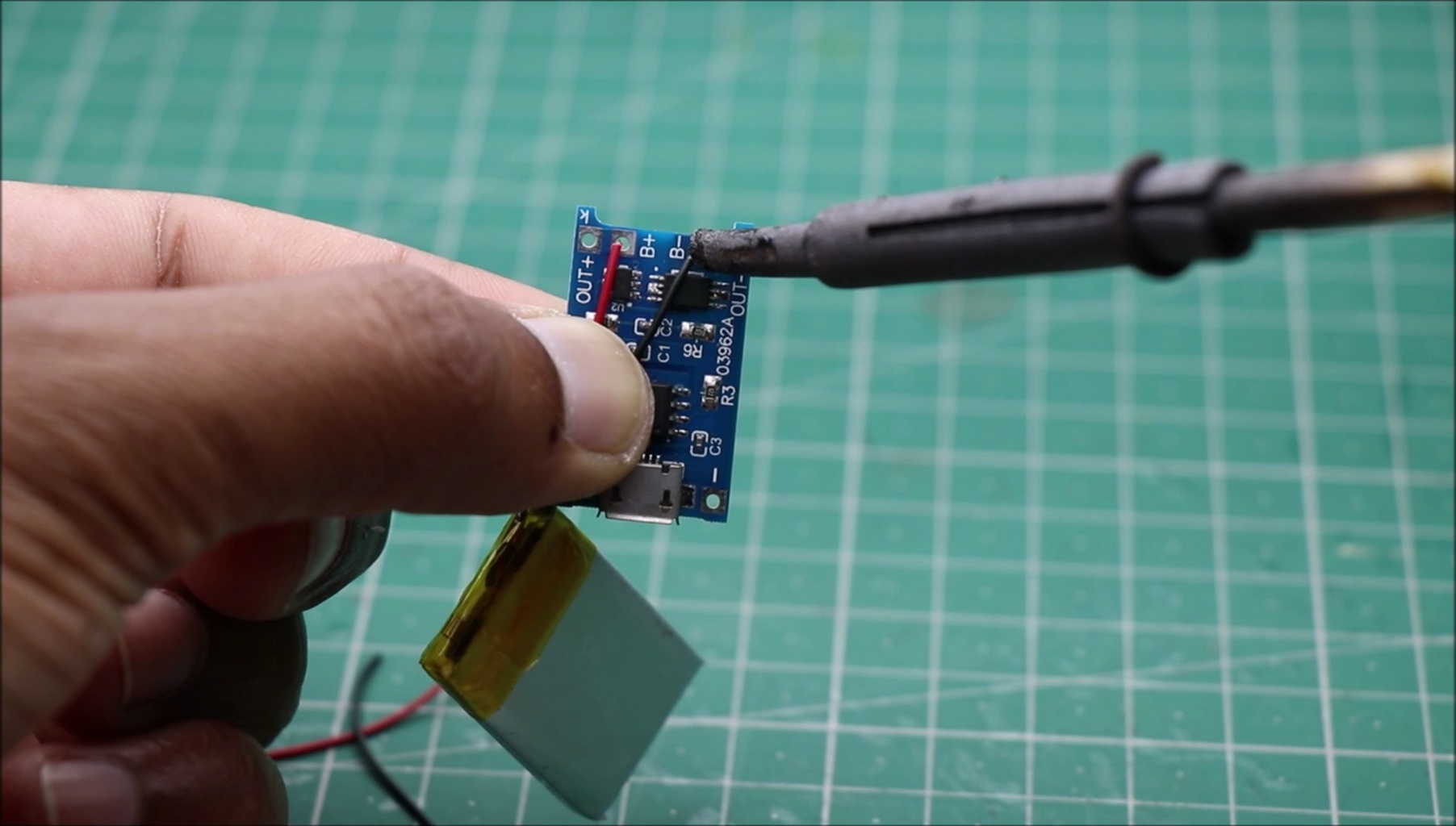
The charging board or tp4056 has 4 terminals that we will be using in this project.
You can start by soldering battery terminals to slots B+ and B- in the board
The output power terminal will be connected directly to the negative leg of led and the other terminal to the led will be connected using a switch
These help in turning on and off LEDs.
The same is shown in the circuit
Note that you can use any of the terminals to use as a switch, anyway it is a very simple circuit.
All we need is a switch that should be able to switch on and off the LED whenever required
Step 3: Building Circuit


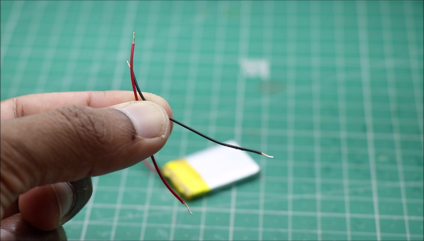

Prepare the battery by trimming the excess wires
Strip the tip of wire using a wire stripper, Solder these tips to the battery charging module
Don't throw away those excess wires that were left over after cutting the battery
Solder these wires to the charging board, Those additional wires that you can see will be connected to the LED later and between them, a switch will be placed
If the length of the wire is not sufficient you can use some other wire that is thin and flexible.
These complete the electronic circuitry that will be installed on the base
Step 4: Placing Electronics


I have designed the frame in such a way that everything fits exactly as per the hardware, so this eliminates the use of glue or any other coupling substance making the entire circuitry clean and compact
From the above steps, you can almost get it how to assemble the board, place it on the base of the frame and lock the edges with the small bump provider at the board base.
After the board is placed you can place the battery on top of the charging board, those additional wires should be long enough to be soldered later
After you complete all these steps make sure the connections are correct, to do so just connect the LED if everything is right the LED will glow and now we are good to go with further steps.
Step 5: Placing the Switch


Now we can place the switch on the slot provided on the frame.
Just place a few drops of super glue on the slot and gently place the switch, allow some time to dry and make sure now to drop excess super glue as these might mess up your entire circuit below.
After this is glued to the base you can connect wires to the switch, note that my switch has 3 terminals, you can connect wires to the 1st and second.
After this step, we can start to add the top panel or in short the plate that holds the LED.
Step 6: Finishing


After you have the base ready we can build the LED holding panel part
it is very easy to make this as i already provided slots in the panel/plate that can hold the aluminum base plate.
Just place the aluminum base plate on the panel and add screws to the slot and tight them using screwdriver
Note: Only use 5mm or less length screws, using large length screws might pierce the lipo battery and adds the risk of damaging the battery
After you install the panel you can bring out the wires from the other base where the control circuit is present.
Wires should be inserted via the slots provided on the LED panel
Solder them with the LED and Couple the top panel using super glue.
Step 7: Checking Light


Some of the batteries might be low at a charge, you can recharge by inserting the USB cable and charging the battery first.
It will take less than 30mins to fully charge the battery.
Now you can use this light by turning the switch on.
To make it look even prettier you can 3d print the body with different colors and give it a final touch by adding a keyring
Carry it wherever you go. Few days back I went on a bike ride at night, I tacked this on side of my bag to increase my visibility to rear riders.
Anyhow the choice of using this is not limited to a specific area!
Step 8: Video Tutorial of Mini Rechargeable LED Light
You can refer to this video tutorial if you have any questions on any steps, if this still didn't help there is always a comments section to connect us together:)
Thank you for showing interest and Happy building this LED light project :)
If your browser is unable to play this video directly paste this link on your URL search tab https://youtu.be/ppNUQjnIf7M

Participated in the
Make it Glow Contest


30 Comments
4 weeks ago
Does it have to have the aluminum plate because it would look cleaner and more professional if it didn't
Reply 4 weeks ago
it would be a lot cleaner, but the problem of heating would eventually melt the pla material!!!
Reply 25 days ago
Oh thanks for telling me love the build keep up the great work
7 weeks ago
Anyway (I'll tell why I say anyway below) thanks for sharing your good work.
Anyway reasons, for sure it will get warm and hot, melt the PLA plastic case. and it will short definetely. Switch has 2 legs one is ground (-) and the other one is connected to positive. But in the video he did it correct. Pls be carefull
Reply 6 weeks ago
Thanks for letting this know..
8 weeks ago
forgot to put a current limiting resistor ? And the LED has an operating voltage of 3.0-3.6 Volts.
And it is also worth replacing the current-setting resistor on the charge board, for a 200 mAh battery, the charge current of 1A is too much
I have not yet remembered that the LED needs a radiator, otherwise it will warm up and fail. Moreover, there is no current limit.
Reply 8 weeks ago
Rimlyanin: could you please elaborate or explain a little more for some of us...
Reply 8 weeks ago
Come on, this is LED 1 0 1, there is nothing to elaborate more, this is primordial knowledge you NEED to have before starting any project that involves electricity...
Google will find your answers in 5 seconds.
Reply 8 weeks ago
Pointless comment. The OP has made a bad Instructable - should be removed (it WILL overheat). Your comment does not help.
Reply 6 weeks ago
IT DOES NOT OVERHEAT, The base of LED gets heated up, But the LED are soldered on the aluminum heat sink with both of the LED pins hauling in the air(base of LED don't touch aluminum plate)
Reply 8 weeks ago
We have a be nice policy. Please be positive and constructive. ALSO: Primordial knowledge- remembering what we’ve always known
“You already know many things, but you do not know that you know. This knowledge comes from a very long time ago, when you still dwelt in the bosom of the Eternal, in light, love and beauty. There you learned everything about your divine origin, your predestination, the work you would have to do on earth to give expression to all the powers of your soul and your spirit. But in coming down to incarnate into matter, you forgot almost everything, and so you need a Master, a teacher, to remind you of what you had already learned about yourself and about the meaning of life. You will all have had the experience, when reading or hearing certain explanations or truths, of something inside you exclaiming, ‘But I know that already!’ Yes, you only had to be reminded, just as embers are rekindled from beneath the ashes.”
And " existing at or from the beginning of time; primeval."
It is wonderful what one can learn in 0.38 seconds
Reply 8 weeks ago
WOW! BenjaminD110 really gave the correct Intructables answer: GOOGLE IT!!!
Question 8 weeks ago on Step 8
Hello, can you give more details to order that kind of LED, that kind of ALUMINIUM PLATE and that kind of MINI SWITCH please?May be an number of production?
Thank you.
Answer 6 weeks ago
its a simple 1w LED and you get the same aluminum heatsink compatible as per the size of LED
8 weeks ago
I am at a bit of a loss to understand the placing of an advertisement, albeit for a fine company, for PCB manufacture when your project has no PCB used other than that of a ready made charger module?
Other than that, an interesting idea but you maybe better served with lower power LEDs that will have a lesser, but still very useable, light output whilst avoiding the issues of excess heat generation……and have the benefit of longer battery life……which may be preferable to fast charge capability. Although the LED is being over-driven when the battery is at full charge of 4.2 v, this LED will bring the voltage of a 200mA battery down to a more friendly level very quickly so the over voltage issues are probably not all that significant to LED life. Having said that though, a current limiting resistor is cheap insurance for any LED project.
Keep building, learning and dreaming. I’ll be interested to see your next project!
Reply 6 weeks ago
YES, Thank you :)
8 weeks ago
how long can you run it before the plastic melts?
Reply 6 weeks ago
No because the LED hovers over an aluminum heatsink plate..
Reply 8 weeks ago
seconds? xD
Reply 8 weeks ago
Well, in his video, the longest it went 'lit' uninterrupted was about ten seconds.