
Introduction: DIY Fiber Optic Light Sculpture


As I mentioned in my previous instructables Fiber Optic and LEDs - a Wall Decoration and Fiber Optic LED Lamp, when I discovered decorative fiber optics I realized that they can be used in a creative way and in projects where I really didn't think they could work. This time I want to propose a very simple application, based on some articles here on instructables.com and on the internet.
but also on the construction of the so-called Fiber Optic LED lamps, on amazon.com for example (I think you all know them):
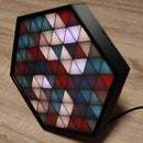
And I don't want to sound immodest when I use the expression "light sculpture" in the title of my instructable but the end result is really memorable, you just have to have the patience to follow my article until the end :)
Step 1: Materials, Components


- 3D printed parts - you can export and use the STL files from tinkercad;
- 3mm diameter decorative optical fiber, the amount needed depends on the construction variant but also on your artistic vibe :) ;
- WS2812 addressable LEDs, 36 pieces for variant 1 and 61 pieces for variant 2, from one piece of self-adhesive LED strip with 60LED/m;
- Wemos D1 mini module,
- DC Power Pigtails Cable, 5.5mm/2.1mm Female Plug,
- 5V/2A power supply. (1.5A is also working...)
Very few components, isn't it?
Step 2: Schematics and Other Info...


I designed two construction variants, one variant that uses 36 WS2812 LEDs and another variant that uses 61 LEDs. The electronic diagrams corresponding to those variants are very simple and you can see them in the pictures above.
You can also see how the pieces of led strip are positioned and how the electrical connections are made between them.
Step 3: Software


To animate the LEDs I uploaded the WLED firmware into the Wemos module.
WLED is an open source software written by Aircoookie (here you can find his github page). It is running on ESP8266 and ESP32 microcontrollers and its only purpose is to control addressable LEDs like WS2812B.
When it is installed on an ESP8266, WLED runs a web server that can be accessed by an app (on iOS and on Android), but can be controlled also by MQTT, Blynk, Alexa and a few other ways.
WLED is the best addressable LEDs controlling application I saw and I’m sure it will continue getting better and better with time.
What I especially like about WLED is that I can try a lot of light effects, and the ones I like can be stored as a program, that can automatically change the effects I saved at a predefined time interval in an endless loop.
Moreover, these saved light effects, called presets, can be downloaded and uploaded later in another WLED installation. So, the effects I used for the two construction variants of my fiber optic sculptures are attached below, you can see them in action in step 5 (rename them to presets.json before uploading to Wemos D1 mini).
And installing it in a Wemos D1 mini module is child's play.
- Access the WLED installer web page with a Chrome browser as up to date as possible;
- Connect the Wemos module with a proper cable to a USB port on your computer;
- Click the "Install" button on the page and check the "Clean install" checkbox if it is not checked,
- Click on the COM port with the Wemos attached and on the "Connect" button;
- Wait a few seconds for the installation to complete.
Done!
Look at the pictures above too.
You can read more about this web server on the WLED wiki.
Of course you can use other effects, for example you can adapt the programs I used in my instructables mentioned in the introduction.
Attachments

Step 4: Construction


I uploaded into the Wemos D1 Mini module the WLED web server for addressable LEDs.
Cut the required LED strip pieces:
- Var.1 - 6 pieces of 6 LEDs each
- Var.2 - 6 pieces of 6 LEDs each and 5 pieces of 5 LEDs each
Then stick the pieces from the LED strip as you can see in the photos above, make the connections between the Wemos D1 mini module and the first piece of led strip and the other pieces according to the electronic scheme. Pay close attention to the connections between the LED strip pieces, make sure the DATA OUT of one strip is connected to the DATA IN of the next strip. Then I connected the power cable. I mounted the WEMOS module at the bottom of the box, placed the support with the addressable LEDs on top and covered it with the optical fiber support plate. Cut pieces of decorative optical fiber, I used different pieces with different lengths as you can see in the photos. Then I inserted both ends or just one end of these fibers into the holes in the support plate in the most interesting way possible, give the artist in you a chance :)
You can follow these operations in the photos above.
Step 5: Everything in Action!
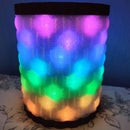
You can see in the video below how the Fiber Optic Light Sculpture is shining :)
A word about the background music in the video.
In recent months I have been looking for different sources to get as easy as possible, and if possible for free, original songs for my future videos. So I found that there are more possibilities to create music with the help of an AI. Among the most interesting services dedicated to this purpose that I have tried were:
- AIVA (Artificial Intelligence Virtual Artist);
- Amper Music;
- Loudly AI studio;
- Ecrett Music;
- Soundraw.
The background music in this video was generated using Mubert Render. I invite you to try it, the results are surprisingly good. An interesting article about how Mubert seems to work can be read here.
Step 6: Conclusions
I hope you have noticed that my construction is really inspired by the construction of the well-known fiber optic lamps that you can find on the net, but still the differences are noticeable:
- Simple and compact construction;
- Very affordable in terms of component prices;
- Practically infinite fiber arrangement patterns;
- Lots of light effects;
- Open source software solution,
to list the ones that seemed most important to me.
And the area of use? It can be a decorative lamp, even outside, a special chandelier, it can be a good exercise for beginners in micro controllers, especially children and ultimately, why not, an original toy.
I hope I did not bore you with this short article.
As always, I am waiting for your questions and opinions.

Second Prize in the
Lamps and Lighting Contest


23 Comments
Question 8 months ago on Step 6
Is it possible to get the 3d model or STL file of each component individually instead of them all in one STL file as it is too large for my 3D printer to be printed all at once.
1 year ago on Step 6
Nice
1 year ago
Very neat project.
I hadn't come across WLED before but had it running on a D1 mini with a string of 50 APA102 LEDs I had sitting around within 20 minutes. The fibre's on order and just setting up the 3D printer to print the parts.
A suggestion : For convenience, how about adding the separate STL files to the Instructable to save potential builders having to register with Tinkercad and splitting the files themselves.
Reply 1 year ago
Thank you for your appreciation!
Also thanks for your suggestion.
And I have to admit something. I really like Tinkercad and 3D designing in Tinkercad. And I would love for others to find out how easy it is to work in Tinkercad. Therefore, at the risk of upsetting some people, in a way, I force those who want to get the STL files to take the first step, that of registering on Tinkercad, and who knows, to try how it works. You probably know that "the secret to getting ahead with something is to get started" or something like that... :)
Reply 1 year ago
Hey, I appreciated having the Tinkercad files. It allowed me to make some simple mods to the design. (I made the box taller to allow more room for the chip, the jack, and a place to mount the chip.)
1 year ago
Well done. I'd like to see and would utilize fiber optic lighting or other fiber illuminating rods but I think the led emitters need to be strong and well directed or to use different kinds of fiber?The light at the base is bright but it fades the closer you get to the end point. You see it with BMW E60/E63 tail lights and ambient interior lighting fiber strips. It's a gradient of illumination instead of a light strip where the brightness is uniform and consistent.
Reply 1 year ago
Thank you
Regarding your question ...
The side glow decorative optical fiber does not behave like a classic one, the one used for data transmission, where the reflection on the fiber walls is almost 100% and the light (laser in general) is transmitted for tens of kilometres. Due to the fact that the reflection of the light of the LEDs is not perfect for the side glow fibers, it is normal for losses to occur along the fiber, and for the light intensity to decrease with distance. Normally the light intensity decreases inversely with the square of the distance (IE quite fast) so it is normal to decrease in the side glow fibers. This is a law of optical physics, you have nothing to do against it, it does not depend for example on the type of side glow fiber optic. You can increase the distance by increasing the light intensity of the LED (high power LEDs), by using focusing lenses placed between the LED and the fiber end or by using 2 LEDs at the fiber ends, this is also the case commercial decorative fibers. Even so, you still have to limit the length of the fiber if you want to have a (relatively) constant illumination along it. And an observation: the price of high power RGB LEDs is quite... high. I'm not saying that making a construction with long fibers with constant luminosity along its entire length is not possible, but that it can be complicated and a bit expensive for an amateur.
In my project I use side glow decorative optical fibers, of relatively small length (from 5cm to 25cm), programmable LEDs WS2812 (relatively low power) and no focus. So it's normal for a fading of light to appear, I honestly wanted it to be like that, I like this effect. And it's simple and cheap :)
PS Maybe you were thinking about electroluminescent fibers? But they only have one color ... I don't know ...
Reply 1 year ago
And in your design, we are putting LEDs on both ends. So, it gives a nice melding affect.
1 year ago
nice project , but i,m stuck after programming wled. i connect wemos to 5 volt no leds on
i connect with usb i get 30 yellow leds on.what am i doing wrong help plz.
Reply 1 year ago
30 LEDs should light up if you use USB or if you use separate 5V power supply. If this does not happen, it means that something is wrong with the connections.
If you manage to eliminate the errors you must continue to configure your WLED installation. Look on your android phone for WLED acces point, connect to it and make the config (for example you must provide the number of LEDs connected to the Wemos isn't it?). You can find all about this configuration in the WLED wiki - https://github.com/Aircoookie/WLED/wiki
Reply 1 year ago
The WLED software has a default of 30 for the number of LEDs. You need to go into the WLED app and set the number of LEDs to 36.
Reply 1 year ago
thanks working now replaced wemos had no power when usb was disconnected
Reply 1 year ago
Great!
1 year ago on Step 6
This project jumped to the top of my waiting-to-be-built list because of its beautiful lighting effects.
However, I ran into several difficulties in constructing it. And several descriptions that would have been helpful were omitted. But hey, if it had been totally easy, it would not have been as fun and certainly not as educational. I THOROUGHLHY ENJOYED making this.
(1) PLA doesn't always print to exact dimensions, due to shrinkage. I had to do a LOT of sanding to get the two insert pieces to fit.
(2) And for the same reason, I had to drill out the holes to get the fibers to fit.
(3) I appreciated having the Tinkercad designs shared with us. I modified the box to have more height, making space for a different size power connector, and more space to mount the ESP8266.
(4) I modified the bar that sticks up from the bottom in the middle, adding two holes, so that I could use screws to secure the ESP8266.
(5) Instead of using a 5V power supply, I simply used a USB cable (https://www.amazon.com/gp/product/B07F9K5VC8/) and wall plug (plenty of those hanging around the house).
(6) After mounting the 6 LED strips to its platform, you'll notice that every 2nd row is slightly offset (if you cut the strips at the indicated lines). It turns out that that's ok; plenty of light still enters the fibers.
(7) I had not noticed the arrows on the LED strip. It's important that you match those to the schematic. (It dictates which end the power source comes from.)
(8) As someone else mentioned, you'll need to buy twice as much fiber than recommended.
(9) Getting the WLED firmware loaded into the ESP8266 was NOT simple. Their website had some problems and I had to use an alternative method for getting it loaded.
(10) Then getting the WLED user interface on my phone to connect to the light box required a lot more reading of the documentation. You have to disconnect from your WiFi network and instead connect to WLED-AP.
(11) After getting the user interface for WLED working, only 5 of the 6 rows would light up. I spent a lot of time looking for bad solder joints, but that was not the problem. The default number of LEDs in the software is 30. You need to go into the settings and change it to 36.
... HAVE FUN! ...
1 year ago
Nice project! I've been wanting an excuse to do a neopixel project and this one was the one to make me do it. I'm waiting for the fibers to be delivered, but I've got everything working and I have learned more about neopixels and an esp board. Thank you!
One thing I would suggest in your write up is to explicitly state to watch the directionality of the neopixel dataline. I didn't notice it in you schematic until a few hours of dinking around trying to figure out way only a single band would like at a time. Doh! I'd nicely lined them all up in the wrong direction! It did provide me the opportunity to learn even more about neopixels. Which is good. :-)
Again, thanks for posting this project and I'm looking forward to creating several of these. Want to place at least one in a public area of my college and have people make their own patterns.
Cheers!
Reply 1 year ago
Hi,
Thank you for your appreciation and comments. I added a short warning text about connecting the data line between the LED strip pieces.
Regards.
1 year ago
nice project.
Reply 1 year ago
Thanks.
1 year ago
That is good idea
Reply 1 year ago
Thanks!