
Introduction: Tetrakis Square Tiling With WS2812 LEDs


I hope the title is weird enough that you will want to know what my project is about :)
Firstly, a few words about tilling or tessellation.
The tilling (or tessellation) consists of the division of the Euclidean 2D plane with the help of some geometric figures, the condition being that between these figures there is no gap but also no overlapping. There may be regular tessellations, obtained by repeating the same geometric figures but also semi-regular in the case of tessellations with several types of geometric figures. Here the difference between tiling and tessellation can be established. The tiling is done with the same geometric figure but the tessellation is made with several geometric figures. For example, a regular tiling known to nature is the honeycombs of bees, using regular hexagons and a very common tessellation is the combination of triangles and squares found in different floor mosaics.
Tetrakis Square Tiling is achieved by joining rectangular isosceles triangles by translating and rotating them. It can also be obtained by joining squares whose opposite and median vertices of opposite sides are joined 2 by 2. The result looks like in the figure below

More information on wikipedia here.
I'm sure you've seen this kind of graphics in many places. Even I used it earlier in my "project". Tetrakis tiling also occurs in quilting, in different models of carpets, textile prints, faience patterns or other types of ceramics. There are hundreds of examples of vector graphics or graphic art. I only saved a few in a Pinterest list here.
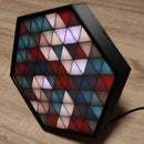
But what I want to show you in this project is a dynamic tetrakis square tiling, made with the help of programmable LEDs. What means dynamic? Because a practically infinite variety of color patterns of the component triangles of this type of tilling can be generated.
If you like beautiful geometric art, this project is for you!
Step 1: Designing
The basic idea of the dynamic LED tiling is that each triangle of the tiling is illuminated by a LED in a certain color. This could show some very attractive models, very varied and sometimes unexpected. I realized the triangles with the help of a 3D printed frame and as LEDs I used pieces from a strip of WS2812 type programmable LEDs. I put these pieces of LED strips under the gaps in the shape of a triangle as in the figure below.

You can see that I have placed in one frame 128 LEDs. I used strips with 60 LED/m with WS2812 programmable LEDs, so a frame size of 188.56mmx188.56mm resulted. Several such frames can be made and interconnected in different ways. I made four such modules and connected them 2 horizontally and vertically. I fixed the modules on an MDF board and placed a smoked acrylic board in front of the modules.
The software part was relatively simple. To control the LEDs I use a Wemos D1 Mini, I could have installed WLED for different effects or adapted some programs that I used in my previous projects but I wanted to try another approach, one that I have tried before in one of my previous projects "Half Square Triangles LED Art". There in the demo program "Four_Symmetry_Demo" I generated some models of LEDs lit in random colors mirrored vertically and horizontally.
In this project I really wanted to generate models as varied as possible, in the most pleasant colors. I used the color palette facility from the FastLED library, from these palettes I randomly chose colors, with the help of the ESP8266.TrueRandom library, that I mirrored either horizontally or vertically, or in both directions. The generation algorithm is as follows:
- I considered that the 512 LEDs are arranged in a 16x32 array, the numbering of the LEDs from every four modules are as in the figure (the correspondence between the serial number of a LED in the strip and the serial number of the LED in the array is as in my project “Half Square Triangles LED Art”)
- I considered a "cell" to be a square containing 8 right triangles as in this figure. 
I chose as the basis for the models a cell, 2x2 cells, and 4x4 cells, randomly selected colors from a color palette: 8 values for one cell, 32 values for four cells, and 128 values for 16 cells, then I displayed them.
- Then I generated non-mirrored or mirrored cells horizontally or vertically or in both directions and displayed them (for the 16 cells I used only one function: mirroring for both directions). A number of 9 functions resulted, which I called randomly, and the resulting pattern remains displayed for 10 seconds.
A real generator of geometric patterns that is very interesting from a visual point of view.
You can find the source code on github here.
I compiled this code with Arduino IDE 1.8.13, ESP ESP8266 library 2.7.4 and FastLED 3.4.0 I also used the ESP8266TrueRandom library to generate values as close as possible to random values.
Step 2: Components, Materials


I used the following parts:
- 3D printed elements, you can download from Tinkercad here and here, I have attached also below the STL files;
- a 6mm thick MDF board, the dimensions I used are in the SVG file attached below;
- WS2812 LED strip, 60 leds/meter, 512 LEDs;
- Wemos D1 Mini board;
- 5.5x2.5mm DC Female Plug with Cable;
- 5V/6A power supply with 5.5x2.5mm DC Male Plug;
- smoked Plexiglas sheet, 450mmx450mm and 3mm thick;
- white colored auto adhesive sheet;
- optional, white wrapping paper (I had about A2 size sheets);
- 3mm screws with nuts and washes (I used some with 35mm length and 20mm length) ;
- wires for connections, heat shrinking tubes;
Attachments


Step 3: Construction


I started with the 3D printing of LED holders because it is, in my opinion, the most difficult part to do:
I sticked the pieces of LED strips and then made the connections between them according to the schematic and the figure above.
I made four such supports for 4 modules.
Then the steps were simpler:
I mounted the 3D printed grid together with the LED holder and the cross-shaped lift piece on the MDF support.
You may have noticed that I did not use the side pieces to cover the LED modules. With their help I wanted to avoid the leteral bleeding of the LED lights but in the end I didn't need it. However, I have attached the STL file just in case.
I sticked the white foil to the Plexiglas sheet.
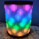
Here I must mention that although I sticked 3 layers of white foil on the sheet, the transparency of the acrylic piece was much too high, the LEDs were too much visible so I also put a layer of white paper between the acrylic and the LED modules. It helped a lot to spread the light.
I installed the Plexiglas lift pieces and the Plexiglas plate.
I made the connections according to the electronic scheme and I uploaded the software in the Wemos module.
You can follow all these steps in the photos above.
Step 4: Operation
There is not much to explain, in the video below you can see the result.
Step 5: Conclusions
As you can see, the result was very good in the end.
I had problems with the light scattering of the LEDs but as I mentioned, I solved the problem with a piece of paper
I also had problems with powering the modules. The first time I powered two modules in series but the consumption of 128 LEDs is much too high and I eventually powered each module separately (as I indicated in the final diagram).
Speaking of powering. 512 LEDs require a lot of current. Luckily, not all LEDs are lit white and at full intensity. I had no problems with the 6A power supply, although I tested the project for days.
I took the photos and the video with the modules on the table and supported by the wall, but it can be also hanged, in the latest version of the MDF sheet I provided a hole for this.
I did not use the wireless capabilities of the Wemos D1 Mini module at all so I will be able to improve the program in the future ...
I hope you will like my project and, as always, I look forward for your feedback and questions.

Fourth Prize in the
Made with Math Contest


6 Comments
1 year ago
This is a beautiful project. Thanks for sharing.
1 year ago
Beautiful project :)
Reply 1 year ago
Thank you!
1 year ago
Great project! Maybe add smoother or even wavelike transition?
Reply 1 year ago
Thank you and you are right. A transition effect would be very nice, I'm still thinking about how to make it simple and interesting ....
1 year ago
So mesmerizing 😍