
Introduction: Square Tiling in WOKWI - the Online Arduino Simulator


A few days ago I published an article about tiling with the help of some right-angle triangles (Tetrakis Square Tiling With WS2812 LEDs) and I asked myself the question, I think somewhat justified, how would it look like built with the help of WS2812 LED matrices.
There are very cheap 8x8 LED arrays, but 16x16 ones can also be found cheaply. Four such matrices could make an excellent display. But the practical realization, from scratch, of the whole ensemble would take quite a long time and honestly I would not put time and money in such a project before I know, at least roughly, what the result would look like.
Luckily for me, and for many others, there are solutions. They are called simulators.
So I would like to present to you the simulation of a generator of colored geometric figures, I think very attractive, and which are nothing more than a regular tiling application, more precisely regular square tiling.
I used WOKWI, it was my first time using it, and in the end, it wasn't as hard as I expected.
Step 1: Concept
The idea I started from was very similar to the one in the “Tetrakis Square Tiling With WS2812 LEDs” project, except that instead of pieces of LED strips I used square LED matrices of different sizes but with the same number of LEDs horizontally and vertically to ease the programming. Also, another value that I considered is the "cell". This is the group of LEDs that I will reflect horizontally and vertically in the LED array to generate symmetrical figures. The minimum cell would be a group of 4 LEDs, 2 rows and 2 columns.

The next cell for mirroring would result by doubling the number of LEDs horizontally and vertically, ie 4x4 LEDs (16 in total)

and finally, the third cell is obtained by again doubling, resulting 8x8 LEDs (ie 64).

This last cell would represent half the horizontal and vertical dimension of the LED matrix that we use, ie 16x16 LEDs.
The following mirroring functions and default display types are shown:
- 2x2 cell without mirroring;
- 2x2 cell mirroring horizontally;
- 2x2 cell mirroring vertically;
- 2x2 cell mirroring horizontally and vertically;
- 4x4 cell without mirroring;
- 4x4 cell mirroring horizontally;
- 4x4 cell mirroring vertically;
- 4x4 cell mirroring horizontally and vertically;
- 8x8 cell mirroring horizontally and vertically;
So a total of 9 functions.
Following the same rules (taking into account the base cell) we can have the following dimensions for the LED matrix:
- 24x24 - ie cells with 3x3, 6x6, 12x12 LEDs
- 32x32 - that is 4x4, 8x8, 16x16
- 40x40 - that is 5x5, 10x10, 20x20
- 48x48 - that is 6x6, 12x12, 24x24
More than 48x48 (the next matrix is 56x56) doesn't work in the Wokwi simulator (maybe not enough memory? I don't know…)
Step 2: Execution
I signed in to the WOKWI site with my gmail account and opened a simulation example from the FastLED library examples - LEDFace.
I saved a copy of this project to my projects in my new WOKWI account (top left menu "Save - Save a copy")
I modified the "diagram.json" file, ie I deleted the three buttons.
I renamed the ino file
I added two files: palette.h and functions.h
When running the simulation I can change the size of the LED array in the ino file, ie by changing the value of the MATRIX variable.
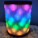
I can also change the "pixelate" attribute of the "wokwi-neopixel-canvas" component ( try "", "circle", "square" to see how the simulation changes visually).
I would like to point out here that I wanted to use a "wokwi-__alpha__-diffuser" component that I found in the "Fire Clock" project, to make the LED light diffusion as natural as possible but unfortunately it did not work for me.
In fact, the documentation at WOKWI is a bit sparse and quite unclear, however it is a great simulator and I really enjoyed working with it. I already had the source code from my project and adapting the code to square matrices was not difficult at all and the fact that WOKWI works with the code that might be used in the future in the physical realization of the project is very helpful.
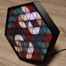
And the result, as you can see in the gif below, is great!

Step 3: An Unusual Usage...


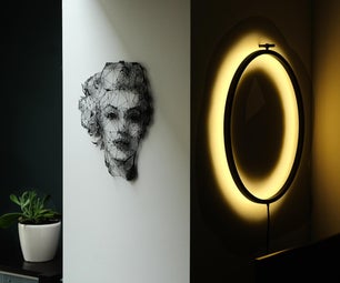
Seeing the results from the gif above, it occurred to me there might be a way to use the generated images from it.
So I simply paused the simulation on an interesting pattern and with the help of paint.net, a freeware image processing program and applying some simple transformations and effects, I got interesting ( and original :) ) textures. You can see some of them attached above.
Step 4: Instead of Conclusions
Of course something is missing! I have to tell you the most important part of the article :)
Here is the link to the simulation on wokwi.com
https://wokwi.com/arduino/projects/317392461613761089
And finally I look forward to your comments and your feedback.

Participated in the
Hour of Code Speed Challenge


Comments