
Introduction: Cistercian Digital Clock


Throughout history, people have invented and used many numeral systems, some well-known: the Sumerian, Roman, Indo-Arabic system (which by the way is used by almost all mankind). But there were also times when other systems were used. In this project I stopped at one of them, the one used by Cistercian monks and, of course, called the Cistercian numeral system .
At the same time with this system, the Indo-Arabic system began to be used, which we finally know was imposed in use.
But who knows? Maybe in a parallel universe it was kept together with the Indo-Arabic system also the Cistercian one and maybe is used in digital watches! :) What would such a watch look like? This is what I want to show you in the next steps :)
More:
- The Cistercian Numerals on Wikipedia;
- David A. King's book - The Ciphers of the Monks: A Forgotten Number-notation of the Middle Ages;
- A Cistercian to Indo-Arabic and Indo-Arabic to Cistercian Converter.
Step 1: The Cistercian Numeral System
As I said, this system was invented by Cistercian monks, a Catholic monastic order, in the early thirteenth century and was used until its abandonment in favor of the Indo-Arabic system. Even at the beginning of the twentieth century it was still used, it is true, very rarely, outside the Cistercian monastic order.
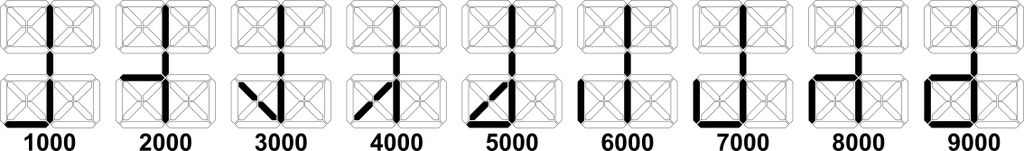
What is interesting in this system? The very compact way in which integers between 1 and 9999 can be written. All four digits are placed on a single character position. Of course, over time several forms of writing of this system were used, I chose one of them in this project, the form you can see in the graphs below.
the ones
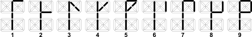
the tens
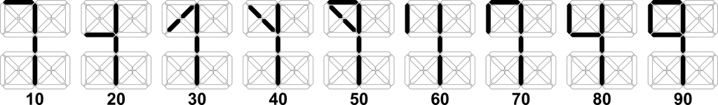
the hundreds
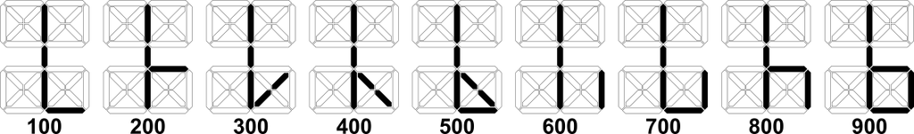
the thousands
So 2317, 1245 or 0958 could be displayed as

In order to use these representations for a digital clock, I adopted the rule as:
- tens of hours to be the number of thousands (bottom left);
- hours should be the number of hundreds (bottom right);
- tens of minutes to be the number of tens (top left);
- the minutes should be the number of units (top right),
Although the Cistercian numerals do not define the zero digit, I considered that the sign is zero is when no LED is lit in squares, exactly as in the example above i.e., 0945. Also 00:00 would look like a line where only the three LEDs on the middle column are lit (which are always ON anyway).
Step 2: What We Need...


- 3D printed parts: the clock body, the LED board, the watch face(s), the support piece, you can download all project files from Tinkercad ( also attached below);
- A piece of CNC-cut smoked acrylic sheet according to the SVG file attached below;
- A piece of white paper cut in the same shape as the acrylic piece;
- WS2812 LEDs, 31 pcs;
- An ESP-01 module;
- A 5v to 3.3V stabilizer module;
- A 2.1/5.5mm DC mother plug with cable;
- A 5V/1A power supply, with 2.1/5.5mm DC plug;
- Connecting wires, heat-shrinkable tube...
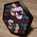
I designed two types of watch faces, one let's say standard, with openings like the widely used digital displays, and a more retro one, which could be assimilated with some drawings or representations from antiquity.
The LEDs I used in this project are remnants of older projects, where I was left with pieces of 2, 3 or even more LEDs that I could not use anyway, so they found their purpose here: )
The ESP-01 module that contains the ESP8266 microcontroller I don't think needs further presentation. It's a module with incredible success and we've all seen it used in countless applications from his appearance in 2014. It is very easy to program and the fact that it has wireless internet and can easily connect to 2.4Ghz networks is an ideal candidate for clock projects, like this, that synchronize online from NTP servers.
You may have noticed that I do not use box-mounted power plugs in my projects, but always cable plugs. I find them much more elegant and easier to use. The ones in the boxes are bulky and ugly (in my opinion) :)
Attachments


Step 3: Construction


I started all with printing the LED board. While the rest of the components were printing, I had enough time to actually mount the LEDs.
Above, you can find the electronic schematic, as well as some graphs in which you can follow how and in which direction I mounted the LEDs on the board, (it was an interesting Hamiltonian Path exercise :) ) how I made the connections to the data line and how I grouped the power lines. Although it does seem complicated, it only takes a little patience and attention. When arranging the power supply wires, I kept in mind that there is not much space between the LED board and the bottom of the body (4 mm). So I had to arrange them so that they took up as little space as possible and I glued them in a few places with a drop of hot glue. Also with hot glue I secured the stabilizer module and the ESP-01 module in the positions provided at the bottom of the body and I made the soldering according to the electronic scheme. I'm done with soldering the power cord also.
You can follow these operations in the photos above.
Then I mounted everything: put the LED plate in the body, pushed the watch face over the plate, placed the piece of white paper, pressed the piece of acrylic over the paper and attached the support leg to the clocks body. Everything comes in pretty tight so I don't need any screws or glue so it's very, very easy to assemble. I made also some photos about this process you can see them above.
An observation. The Cistercian Numerals were also written with a horizontal middle bar. The construction allows the positioning of the clock also for this way of writing, just turn the clock by 90 degrees :)
Step 4: Software

I know that since Arduino Core for ESP8266 2.4 there is support for sntp, but if you search you will see that even now many use external libraries to get the exact time with ESP8266 from an NTP server.
I know there are a few wifi managers so that there is no need for hardcoding in the source for the wifi-user and the wifi-password.
But it seems that sntp support still has problems and there is no clear documentation and examples (there is only one) about the functions they offer and wifi managers have the problem that they do not work well on all mobile phones and also it is not easy to define your own html pages and web variables to use in your own programs.
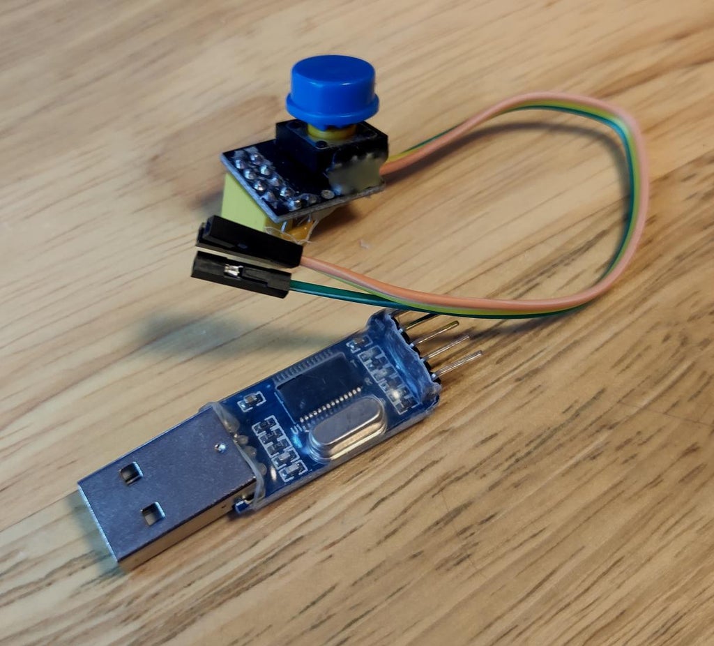
So I will continue to use in this project the web config interface based on the work of John Lassen - ESP 8266 Arduino IDE WebConfig. It is very stable, easy to configure, works perfectly on all mobile devices either IOS or Android and your own html pages can be defined very easily. I was also inspired by ESP8266-Arduino-Webconfig and Internet-of-Things-with-ESP8266, which are also based on John Lassen's code. Apart from the actual code for getting and processing the exact time as well as the code for the webserver, the program contains only the LED display part according to the rules I presented in the second step. There are also a few small effects to display the time, you can watch them in the video at the end of the next step. The source code is on github, you can download it from there. The program can be loaded with an USB to serial module you can see in the photo below, this is exactly the method I used in my instructable "Automated Perpetual Calendar".
I used Arduino IDE 1.8.13, Arduino Core for ESP8266 2.7.4 and FastLED 3.4.0. With the settings you can see in the picture above the program is compiled and loaded in the ESP-01 module without problems.
Step 5: How Is Everything Working...
When we start the clock for the first time or if we are in a new place with another wifi router where we have other credentials than the stored ones, the ESP8266 microcontroller from the ESP-01 module will try for a while to connect, failing this, it will switch to Access Point mode. An effect will appear on the watch screen in which white lights light up randomly (softtwinkles).

At this moment if we have a device with wifi access (laptop, tablet, mobile phone) we can connect to the access point with the name “CistercianClock- *” (the password is admin1234),

we start a browser (preferably chrome) and try to connect to the address 192.168.4.1 If everything is fine we will be able to access the main clock configuration page.

We must first connect to the router. So let's go to "Network Configuration".
We are waiting for the network scan to finish and our wifi router appears, we click on its name, it will be pre-filled at the top of the page. Enter the wifi password and click on the "Save" button

Now we can have 2 situations:
1. We wait a while, the clock will restart, it will display the same effect, and if we try we can access the same address 192.168.4.1 but now the ESP8266 microcontroller is at the same time in Acccess Point mode and Wifi Client mode. If we access the "Network Information" menu item we can see what address the clock received from the DHCP server of our router.

At this point we can restart the clock (remove and insert the power supply from the socket), if the color effect in the picture (pride) appears on the display, it means that the clock has connected to the router and is trying to pick up the exact time.

If the operation succeeds then the hour and minute will be displayed on the display, if not, the color effect from the picture above will continue to appear.
2. After a while, the clock freezes and the effect on the display “freezes”. All we can do is restart the clock. If the credentials for the router have been saved, then the same "pride" effect will appear on restart as in the picture above. If the exact time is taken, it will appear on the display otherwise the color effect will continue to appear. However, we do not know the IP address received from the DHCP server. But we can use a local network scanning application on the phone (Android). You can see in the picture below how the watch's IP appears.

Now that the clock is connected to the net we can explore the settings in the administration menu.
We have already talked about "Network Information", where we will find information about the main parameters of the connection. In the next item, “NTP Configuration” we can set values regarding: the time server to which the clock will connect, how much time will pass between two consecutive requests to the time server, what time zone we are in and also if we use daylight saving time and winter time (daylight saving). So the clock can be used anywhere in the world to display the exact time.

At "Manual Time Settings" we can enter what time we want, mainly this option is for the case when we do not have internet access or we are in a place without internet or we do not have internet connection for a longer or shorter period of time.

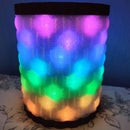
And the last menu item "Display Setting" can be used either to change the color displayed by the LEDs of the clock or to switch the display in a very colorful way that I called "rainbow effect".

Below you can watch a short video with the "live" operation of the clock.
Step 6: Alternative LED Support


By far the most difficult construction operation this watch has is the interconnection of the LEDs on the support. It requires a lot of patience, takes a long time (I lost two afternoons with this phase), a lot of soldering, and it is quite difficult to group many wires so that they are arranged nicely under the LED support. The solution is of course the use of a PCB. But because I don't like to solder SMD components, I also designed the PCB for the pieces of strip with a single LED :) I used pieces of LED strip because I had them at hand but you can use modules that are much easier to assemble and solder. E.g.:
- Pixel WS2812B Breakout Board;
- WS2812B smart RGB LED breakout board;
- WS2812 5050 RGB LED Driver Development Board;
- WS2812B 5050 Full Color LED Module;
- WS2812 WS2812B WS2811 5050 RGB LED Module;
There are many options…
Of course, if you use other types of modules, the PCB needs to be redesigned.
After all, if we compare, the price of pieces of led strip price is the cheapest, especially if they are left from other projects as I said before.
Because I do not have standard realization possibilities (etching with ferric chloride) I resorted to a CNC. I don't want to go into details because there are a lot of howto's about making amateur printed circuits boards on CNC, I found two here on instructables for example:
I attached below the pdf file (a last version that is correct) that I used and I also took some photos with this construction version.
It didn't work out perfectly (I was wrong at the beginning when designing the PCB) but it's pretty good and I'm sure you'll notice that everything is much simpler. The intermediate slim frame (STL file below) in the photos is necessary to slightly raise the face of the watch from the PCB, it may even be a common body with the watch face that will have a narrow edge in this way.


Step 7: Some Conclusions
You might say, "But why?" With the same energy, a normal 4-digit digital clock could be made.
Because it's interesting, I could answer, because it's a logical challenge, because it's unusual, because it's geeky, because it brings a little "strange" to my desk. Initially, I thought that I would not be able to get used to it but to my surprise in a few hours I could read the time almost perfectly. That's when I noticed how intuitive is the way the numbers are written.
Also consider the following scenario.
Friends come to visit you and ask you what that object on the desk is. "A clock", you will answer. "Oh! And what time is it?" You will answer with the exact time after a short glance at the clock. “Wow! How?" And this can be a great start to a conversation about history, writing systems, time, parallel worlds, life, universe, everything :)
What do you think!
I am waiting for your reactions and questions and as always, I will try, as much as possible, to be helpful.

Second Prize in the
Microcontroller Contest


41 Comments
13 days ago
it's beautiful!
Reply 12 days ago
Thank you!
1 year ago
love the project however i think i found 2 bugs in your code. Not sure where it is though. In the manual time setting when you set the "hour" to a certain hour and click save. It will refresh the page and increment the hour +1 to whatever you set it to. If i set it to 13 and click save it will save it, refresh and set it to 14 and then set the time with the lights to 14.
Also I see you have a daylight savings time I believe this is set for DST in Europe? For example Uk changes it October 20th 2022, USA changes it November 6th 2022, Australia changes it October 2nd 2022. I don't think it handles this based on the NTP pool we select?
Reply 1 year ago
Thanks for the appreciation.
About the bugs ...
I only thought of the manual setting as an extreme option for using the clock. When I am using an ESP 8266 I'll probably have a wifi nearby right? In general, I used the manual setting only for tests, for example to check if the display of different numbers is correct. But if you really want to use it longer, then you should set the time zone to zero, disable the DST and then the time that is set in the "Manual Time Setting" interface will not change.
As for the DST ...
Indeed in the code I used the calculation only for the Europe area but nothing stops you from doing a little subroutine that will return false if the current date is out of the DST action and true otherwise. In fact, it is hilarious how often the data to which daylight saving is applied changes in different parts of the world. For example, in Europe in a few years it will be abandoned, so it will not be a problem, at least for me :)
Reply 1 year ago
Thanks so much for the reply. That is fair amount the manual time. I will just comment this out.
For the DST time. I will see if i can modify it but the skill level I see that you have is well beyond me and I wouldn't be able to do that. I do know of an NTP library that does support Europe and America Timezones maybe I can try and implement that.
Thanks for the great project
Question 1 year ago
Hello, can you upload the stl files here please? I don't have a thinkercad account.
Answer 1 year ago
Check steps 2 and 6. Cheers!
1 year ago
Four weeks later, I finally got the watch together. But what I noticed already during the first tests was that the very first LED in the row always flickers. I first thought that this was because of the LED, that it might be defective. But when I replaced it with another one, the replacement showed the same behavior. So also in the almost finished clock: The first LED (i.e. the rightmost LED in the top row of digits) flickers. Do you perhaps have an idea what this is due to?
Here's a video of my clock: https://www.youtube.com/watch?v=8bOVeM8NGhw
Reply 1 year ago
Did you used the 3k resistor as in the electronic diagram?
Sometimes it is good to use a series resistor (330-470 ohms) with the DATA IN of the led strip.
Reply 1 year ago
Yes, I wired a 3k resistor as shown in the schematic. I'll try a 330Ω, 390Ω and 470Ω resistor from the 3k resistor to DATA IN of the LED stripe.
But I guess it's more of a timing problem with my WS2812_B_ (!) LEDs. So I'll try this also: https://github.com/FastLED/FastLED/issues/306
Reply 1 year ago
Yes, sometimes adding
#define FASTLED_ALLOW_INTERRUPTS 0
helps with some flickerings
2 years ago
It's such a wonderful and strange clock at the same time. As a mathematician I'd love to build this clock. Can you tell me anything about the size? When I import the tinkercad files in Cura I'd estimate the height at approx. 6.5 inch?
Reply 2 years ago
In the image below you can see de main part's dimension in inches. I don't know where the 6.5 height comes from :(
2 years ago
Do you not have 5 excess LEDs in this clock, in the 10s of hours section? It seems to me you only need the LEDs to show 1 and 2.
Reply 2 years ago
Hi
Even if I didn't mention these in the article, yes, there really are a few extra LEDs and that's for two reasons:
- One would be that I wanted it to be a nice symmetrical, balanced display
- The second would be that you can use the clock as a stopwatch from a maximum of 9999 seconds by slightly modifying the program (maybe in a future update...)
I hope I have clarified your question
2 years ago on Step 7
Great work :)
Reply 2 years ago
Thanks!
2 years ago
You have created an enigmatic work of art! I do have a question. There is a piece of paper over the LEDs that acts as a light diffuser, and over that is the smoked acrylic. When the LEDs are off, does the surface appear as completely black or is it possible to see the cutouts at all underneath the acrylic? Thanks!
Reply 2 years ago
Hi,
as you can see from the photo nothing is seen under plexiglass maybe just a little texture of the paper but you have to look very carefully for this to notice :)
Reply 2 years ago
Thanks! Sorry to keep asking questions, but I would like to make this someday. Can you tell me how to select the particular shade of black to specify when purchasing the smoked acrylic? I think there are different levels of opaqueness and it should be important to choose the right one. Thanks again!