
Introduction: 3D Printed Triple Shaft Stepper Motor Mechanism With Arduino Control


I bet many of you have heard about (maybe even seen or work with) biaxial steppers.
These small mechanisms consist of 2 stepper motors that independently drive two concentric axes. They can be bought very cheap online on amazon or aliexpress. They are mainly used in car instrumentation to display 2 values simultaneously on a dial, but I also found many other interesting projects made with the help of these devices:
- World Stepper Clock with NXP LPC845
- KLOK
- DIY Two-Needle Dial with Arduino
- Behind the Canvas: Making of “60 Billion Lights”
Inspired by these projects, I thought of making a mechanism not with 2 but with 3 stepper motors to rotate three concentric shafts.
Step 1: Components I Used


- 3D printed parts - you can download them from Tinkercad;
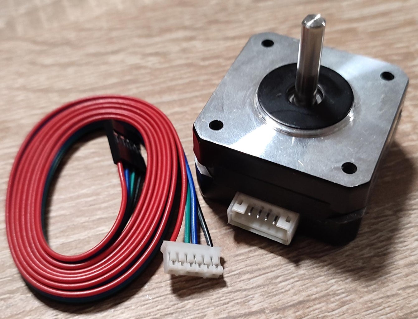
- 3 pcs. 17HS4023 NEMA17 stepper motors;
- 3 pcs. 188mm GT2 timing belts;
- 3 pcs. GT2 pulleys with 20 teeth with a 5mm hole;
- M3 threaded rods;
- M4 threaded rod;
- M3 and M4 nuts;
- Washers M3 and M4;
- 1 pcs. Arduino Nano CNC v4 module;
- 1 pcs. Arduino Nano module;
- 3 pcs.Stepper motor driver A4988 2A + radiator;
- 1 pcs. DS3231 RTC module;
- Female to Female Dupont wires;
- 1 pcs.Power supply 12v/3A.
Step 2: Some Design Notes
The mechanism is mostly built from 3D printed parts. I used PLA filament, although maybe for better resistance PET-G would have been indicated. But it works ok anyway.
The most delicate part of the design was the shafts. For the profile of the gears on the shafts I used the GT2 pulley generator web page where I generated a profile for a standard GT2 gear with 36 teeth with a different inside bore diameter depending on the axis (4.2 mm, 8.2 mm, 12.2 mm). Why exactly 36 teeth? Because I will eventually use this adapter to build a clock. Of course, the number of teeth can change depending on the application. The most common stepper motors have a step of 1.8 degrees, which means 200 steps per rotation. I wanted to have a number of steps divisible by 60 so that the number of steps would make an integer. So I mounted a 20-tooth GT2 gear on the stepper motor shaft. Three belts transmit the rotational motion of the motor to the shafts (on which is the pinion with 36 teeth), the number of steps becomes 360/(20/36*1.8) = 360 steps per revolution, so one second would mean rotating the motor shaft by 360/60 = 6 steps.
Another important value of the mechanism is the distance between the axes of the two pinions, the one on the motor with 20 teeth and the one on the axis with 36 teeth. To calculate this distance I used the Timing Pulley Distance Calculator web page Since I used 3 188mm long GT2 belts it resulted in a distance of 69.297mm. However, it must be taken into account that I also needed a little clearance to facilitate the installation, so on the motor supports I made 4 small channels, not just simple 3mm holes..
Of course the dimensions can change slightly depending on what you have on hand: motors, belts... you can copy and edit the project on Tinkercad.
Step 3: Let's Make a Watch
As I wrote above, my first thought when I imagined this mechanism was to use it to make a clock. Stepper motors can be very well used as clocks. There are highly precise motors that can be controlled to rotate in very small increments, making them ideal to use in applications where precise positioning is required. This property of stepper motors makes them well-suited for use in clock applications, where the motor can be used to move the hands of the clock with precise timing. The stepper motors can be controlled by a microcontroller to rotate the hands of the clock in precise increments based on the current time.
Using three stepper motors allows for greater control over the positioning of each hand, as the motors can be controlled independently to rotate the hands to the correct positions. Also using separate motors for each hand of the clock allows for greater flexibility and precision in the positioning of the hands, as the motors can be controlled independently.
Finally the three axes with independent rotation are perfect for this purpose and the stepper motors that have a fairly high rotation torque allow the use of long hands and therefore the construction of a big watch 🙂 All I had to do was print some hands (printed in several pieces that l then glued together), numbers, line pointers...
....the files are on Tinkercad, hands and numbers.
and make a program for the Arduino Nano so that everything would work fine. About all this in the following steps.
Step 4: Construction of the Mechanism


I have started it all by 3D printing the shafts and the support for them. I used 0.2mm layer height and 50% infill.
Then I moved on to assembling the mechanism. To make things easier I made a video about this, it's a bit long, if you have a bit of patience you can watch it but even without the video I think the assembly is quite intuitive.
Some observations…
When mounting the main shaft I used M4 washers with the larger outer diameter to strengthen the position of the shaft ( penny washers)
I struggled a lot with the cutting and shaping of the M3 threaded rods, I used a metal saw and some sandpaper but I think this phase can be improved so that the nuts screw in more easily.
To screw the rods into the stepper motors, I used a small hack, I screwed a nut on the end of the rod, then a washer and another nut, I tightened it well and screwed the rod with the help of the top screw. (see also... How to screw in a threaded rod? )
I didn't stretch the belts too much so as not to force the main rod just enough so that the belt teeth wouldn't jump off the gears.
You can see a video that I had to reposition the gear several times on the motor so that it would be at the same height as the gear on the shaft.
After I assembled everything (see also the electronic part in the next step), I asked myself how can I fix all the mechanism on the wall to make the clock. For this, I designed an intermediate plate, which is fixed in the wall, either with screws, with the help of holes, or as I tried the first time, with the help of pieces of double-adhesive tape that did not hold. So in the end it's all down to the screws :)
...files on Tinkercad...
I haven't printed the cover from the page, but whoever wants to finalize the watch can use it.
I fixed the mechanism to this plate with the help of three M5 screws, nuts and washers and dome risers. I also mounted the clock hands.
I have attached some photos about these operations.
Step 5: The Electronics


The schematics is below
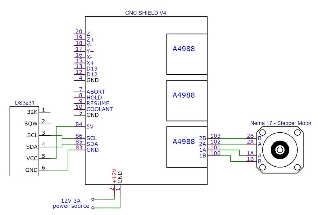
As you can see, I just made some quick connections: with Dupont wires between the RTC module and the CNC shield and with cables between the motors and the CNC shield, you can see in the photos above how it looks.
Some clarifications...
Because the RTC module came without a battery, I used a CR2032, but it is not rechargeable. The module instead needs a LIR2032 (rechargeable), I didn't have one and so I had to disable the battery charging circuit, that is, I broke a connection on the PCB, the connection between R5 and D2 as in the picture below.

More in this post on the Arduino forum DS3231 CR2032 vs LIR2032 warning! Is your module killing the battery?
Even the CNC shield is not perfect, I bet you know 🙂 , but for what I wanted to do with it, no modification was needed (for example, activating the micro-stepping). I have to admit, however, that I made the changes in the article just to see how the watch behaves when using the micro-stepping, I tried with 1/2 and 1/4 steps but in the end I used the full step.
Stepper motors, if they work in full step mode, have the advantage that when the motor stops, they will be locked in position and thus facilitate the independent rotation of the three axes. In the case of micro-stepping, this would be more difficult. Also at full step the holding torque (the motor can hold the load in place) is at maximum, at micro-stepping this force drops drastically. The advantage of micro-stepping, however, is that the movement of the motors will be smoother and less noisy.
It is also necessary to adjust the reference voltage, after which the maximum current that will pass through the motors is determined. I adjusted the vref of each a4988 driver to the value of 0.64 volts which corresponds to a maximum current of 0.8A on each motor (0.64x1.25) More here: How to set VRef for A4988 and DRV8825 stepper motor drivers.
For the power supply, it turned out that a 12V 36W power supply would be enough - according to this article: How to choose a power supply for my stepper motor?
I also had an unpleasant surprise during the tests... The motors didn't want to work properly, they were spinning wildly, humming, stopping and starting again... I didn't understand why. In the end, I realized that the wires from the connection cables between the CNC shield and the motors have two wires reversed at the plug on the motor side. I arranged them correctly and everything worked perfectly afterwards.
You must not forget the fact that the CNC shield is the simplest and cheapest option to control step by step motors. It cannot compete in any way with the boards that are used in desktop CNCs or 3D printers. So the motors do heat up a bit, make noise, there are some high-frequency whistles, it's normal to be like that.
The library I use for driving the stepper motors allows 2 ways of rotating them: with constant speed and with acceleration/deceleration. I tried both versions, with the acceleration/deceleration mode the motors are less noisy and the oscillations of the clock hands caused by starting and stopping the motors are considerably reduced. I used constant speed for the hour and minute hands and for the second hand acceleration/deceleration.
And one last warning. The use of high rotation speeds of stepper motors should be avoided. With the increase in speed, the running torque (rotational force) decreases and at some point the motors will lose steps and at some point may even stop. The stepper motor has high rotational force at low speeds (contrary to normal DC motors which at low rotational speeds have low rotational force).
Step 6: How It Works
I started the clock in three stages:
- Uploading the actual time in the RTC module;
- Manual homing;
- Effective start.
I fixed the exact time by running a sketch that initializes the real time clock at the time I want. This update can be done by setting the exact time to the date and time of sketch compilation, only there will be a difference of a few seconds (7, 8 seconds) compared to the exact time, maybe it is not really annoying. It can also be initialized directly by an explicit date and time from the serial terminal. I used the last method.
The sketch for setting the RTC module can be downloaded here on github.
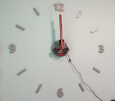
The manual homing is nothing but the manual rotation of the clock hands at 12 o'clock, and then I would consider this positioning to be the home of all motor movements when starting the clock program (see photo)
When the program actually starts, the time is read from the real-time clock, the motors rotate the hands in the positions corresponding to the time read, then all the hands of the clock move with the passage of time. The second hand rotates every second to the position second*6 steps, the minute hand moves one step every 10 seconds and the hour hand moves every 2 minutes one step...
After a power drop, this manual homing must of course be redone, otherwise the clock will start from a random position. Luckily, after homing, reading the exact time won't be a problem, it's just saved in the RTC module, isn't it? 🙂
The main program I uploaded to the Arduino Nano module can be found here on github.
I did not use a limiter or sensor for homing the three stepper motors. I wanted the mechanism to be simple, easy to make and flexible to use for other projects as well.
To connect the Arduino Nano with the real time clock module I used the DS3231 library
To drive the three stepper motors I used the AccelStepper library
In the above short video you can see how the clock is working.
Step 7: Instead of Ending
What else could be added?
Maybe that the watch application of this mechanism is not perfect, but I wanted to show that it can be done.
And even more, you realize now how simple it is to make a clock that goes backwards? Or a clock that displays 24 hours at once? Or a decimal clock (10 hours with 100 minutes and 100 seconds)? With very small changes they can be done without problems.
The most important utility would be the possibility of simultaneously displaying three distinct values on a very large dial, for example temperature, humidity, atmospheric pressure, by the way, biaxial motors were invented for this, right? We can drop one engine and have 2 displayable values at once or add one more engine or (why not), with my design, even six engines could be used but of course with substantial modifications :)
I hope you will appreciate my project, you know you can ask me questions, I will answer them the best I can with pleasure.

Runner Up in the
Anything Goes Contest


3 Comments
2 months ago on Introduction
Nice job, Andrei. When I load your .obj or .stl files into my Cura slicer, however, the objects are quite large. Can you recommend a scaling factor to bring them down to actual printable size? Also, would you consider separating the four objects into separate .stl or .obj files?
Reply 2 months ago
You can save the components if in Tinkercad editor you click on them and export ""only the sexted object". The dimension are in mm, there is no need to scale the components.
3 months ago
Nice job.
A tip: When making large hands, usually you will see opposite the Pointer side a nice fancy shape short but wider than the pointer.
This is not just decoration, it acts as a balance or hides a balance.