
Introduction: LATTEblet- Handheld PC


Hey, what's up you guys?
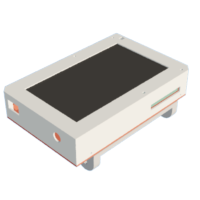
So this is the LATTEblet which is a Handheld PC-Tablet that runs Windows 10 and can be used as a proper PC to run all things like Microsoft Office, Software, Games, etc, or can be used as a Tablet for media consumption.
The heart of this Project is a LATTEPANDA 3 DELTA single board computer that is connected with a 7inch IPS Display which is made by LATTEPANDA.
There's a battery inside this setup that makes this whole thing portable.
It's completely a touch device but we can dock it and connect a mouse or keyboard with it as well, along with an external monitor through HDMI Port or an extension hub via provided Type C port.
The Goal here was to build a properly functioning Handheld PC that can be used on daily basis for a bunch of tasks like content consumption via youtube and lite retro gaming.
Ipad is what I've been using for these above-mentioned tasks so I wanted to make a DIY Device that can replace the good old Ipad in both performance and spec-wise.
This Instructables is about the whole built Process of this LATTEblet Handheld PC-Tablet, let's get started.
Supplies
Following are the materials used in this built-
- LATTEPANDA 3 DELTA SBC
- LATTEPANDA 7' EDP Touch Display
- 3D Printed Body
- M2 Screws
- SSD M.2 Key
- Lithium Ion 12V battery pack
- DC Barrel Jack
- Rocker Switch
- Toggle Switch 12x12mm
- M3 Threaded inserts
- Diode M7
- Indicator LED 0805
- Resistor 1K 1206
- Keyboard and mouse
- LATTEPANDA Power Supply
Step 1: 3D Design


We start this whole project by first Designing the Base Body in Fusion360.
LATTEPANDA Screen was modeled first and then the whole body is made according to screen fitting and LATTEPANDA 3 DELTA placement.
I won't go into detail about how this was created and how to use fusion360 but you can check out Lars Christensen's channel for getting started.
This whole project is based on four different parts that are the Base Body which holds everything from Screen to LATTEPANDA SBC, Battery, and other components, Lid that closes the Base body from the back side, Battery Clamp that holds the battery and the Switch Holder that is a holder for the main ON-OFF switch.
The base Body is made out of white PLA with a 1mm Nozzle that gives this part thick walls and more structural strength.
The same setting was done for Lid but it's printed with Transparent PLA with a finer 0.4mm Nozzle.
Battery Clamp and Switch Holder both are printed with black PLA with a 0.4mm Nozzle as well.
Because of the LATTEPANDA 3 DELTA thickness plus display thickness, this device is a little bit thicker than the existing tablet PC in the market, Next version will tackle this issue and will be much slimmer.
The CAD file along with the 3MF files are all attached for modification and 3D Printing.


Step 2: Display


For this project, I used the official LATTEPANDA 7' EDP Touch Display which is an IPS Display with a 1024 x 600 high resolution, and high color saturation, achieving excellent picture quality.
It even has a Capacitive Touch Layer, which we will be utilizing for the touch part of the project.
This display needs adriver to run so you can install them from here-
http://docs.lattepanda.com/content/alpha_edition/drivers_and_software/
Folks at DFRobot were kind enough to send me this display for the LATTEblet Project so huge thanks to them for the support.
You can check out more details about this Display from the below link.
Step 3: LattePanda 3 Delta


As for the Brain of this project, LATTEPANDA 3 DELTA is being used here which is a Single Board Computer powered by an Intel Celeron N5105 11th Gen Mobile Processor, Its is an X86 Processor that can handle all sorts of task that is being executed on a regular PC.
LattePanda 3 Delta uses 2933MHz high-frequency LPDDR4 8GB RAM with 64GB Onboard storage.
It runs default windows 10 but we can swap it with Linux which is awesome.
LattePanda 3 Delta uses an M.2 B Key instead of an M.2 E Key and can connect to the 4G or 5G module, we can even add a graphic card by using an NVMe Key M Extender Cable to PCI-E x16 Graphics Card Riser Adapter.
SPECIFICATION
- CPU: Intel® Celeron® N5105
- Core: 2.0~2.9GHz Quad-Core, Four-Thread
- Graphics: Intel® UHD Graphics (Frequency: 450 – 800MHz)
- Memory: LPDDR4 8GB 2933MHz
- Storage: 64GB eMMC V5.1
- Expansion Slots: 1x M.2 M Key, PCIe 3.0 2x, Supports NVMe SSD 1x M.2 B Key, PCIe 3.0 1x, USB 2.0, USB 3.0, SATA, SIM, Supports SATA, 4G & 5G module
- Connectivity: 1x Wi-Fi 6 @ 2.4GHz &5 GHz(160MHz) 1x Bluetooth 5.2 1x Intel Gigabit Ethernet
- USB Ports: 2x USB 3.2 Gen1 Type A 1x USB 3.2 Gen2 Type A 1x USB Type C, Supports PD, DP, USB 2.0 1x USB 2.0 Pin Header
- Display: 1x HDMI 2.0b: Up to 4096x2160 @ 60Hz HDR 1x DP 1.4: Up to 4096x2160 @ 60Hz HDR 1x eDP: Extendable Touch Displays up to 1920*1080
- TPM: built-in TPM(2.0)
- Co-processor: Arduino Leonardo ATMEGA32U4
- Audio: Microphone + Headphone Combo Connector
- GPIO & Other Features: 12x Analog Inputs* Up to 23x Digital Input/Output (7 PWM)* 1x UART 1x I2C 1x SPI 1x Audio Connector 1x 4-Pin RS232 Header 1x Fan Port (4 Pin 1.25mm PWM 5V) 1x 4-Pin Header (Power and Switch)
- OS Support: Windows 10 & Windows 11 & Linux
- Dimension: 125 x 78 x 16mm
- Operating Temperature: 0°C~75°C
DFRobot reached out and provided this SBC for the current project, do check their site for getting your Latte Panda 3 Delta.
https://www.dfrobot.com/product-2594.html?tracking=62f36d08e4165
Step 4: SSD Upgrade


LATTEPANDA 3 Delta has 64GB Onboard eMMC Storage, which sounds nice, but it's not great if there's an OS loaded in it: Windows.
It's kind of mandatory to do an SSD Upgrade to this device if you want to run it regularly and load stuff into it.
I'm using a cheap 20$ SSD made by Simmtronics, its a 128GB M.2 SSD that will be plenty in the current setup.
- We place the SSD in the M.2 B Port and push the SSD into its socket carefully.
- Next, we screw the SSD in its given screw terminal and that's pretty much the SSD upgrade process.
- Later we have to create a new volume for the SSD to work in the disk manager.
Check out this small Guide to setup SSD in Disk manager-
Step 5: Adding Display to Base Body


- We start the Assembly by first adding the Display in the Base Body and then using hotglue to hold it in its place.
Step 6: Connecting Display With Latte Panda


- Next, we connect LATTEPANDA 3 DELTA with the display by the provided eDP Cable.
- Then we connect Touch Cable to LATTEPANDA.
Step 7: Body and Latte Panda Merge


- We then place LATTEPANDA in its place and add fiber tape to hold down the eDP Cable and touch the cable down so we can add a battery on top of it without damaging the cable.
- Next, we add M2 Screws to secure LATTEPANDA in its place.
Step 8: Power ON-OFF Switch Assembly


- We prepare the Power ON-OFF switch by adding the switch into a PCB and soldering a CON2 wire with it.
- We add the Switch to the Switch Holder and secure it in its place by using Hot Glue.
Step 9: Adding Main Switch and Charging Port


- Next, we add DC Barrel Jack which is for charging, and Rocker Switch to the base body.
Step 10: Adding Power ON-OFF Switch


- We add the Switch Holder assembly on the base body and secure it in its place with Hotglue.
- Next, we connect the Switch CON2 Port with LATTEPANDA's SW Port.
Step 11: POWER SOURCE- Battery


The voltage range of the LATTEPANDA 3 DELTA power input connector is 11 to 15 volts which can be FED through a 4 Pin JST connector which is on the Latte Panda.
We use a 12V Battery Pack consisting of 3 Li-ion Cells each of 3.7V. These cells are connected in series with a BMS that controls the charge and discharge cycle of the pack. Each cell has a capacity of 2900mAh so this pack is an 11.1V 2900mAh Pack, after full charge, it can reach up to 12.6V which is under the LATTEPANDA power input threshold.
As for charging this Battery pack, an external DC Jack was connected to Battery Pack's positive port with an M7 DIODE in series. an LED indicator and resistor were also added on the DC Jack side to indicate Charger is plugged in.
There's also a CON2 connector that is between the GND of the battery and the GND of LATTEPANDA, idea here is to connect a rocker switch with this CON2 to manually break the continuity, this is a kill switch that turns OFF the main power by disconnecting the battery from the LATTEPANDA.
Step 12: Battery Holder and Assembly


- We start the Main Assembly by adding the Battery pack to its Battery Clamp by using some hot glue.
- Place the Battery Clamp inside the Base body and secure it in its place by using four M2 Screws.
- At last, we connect the 4Pin JST connector of the battery pack to the LATTEPANDA power input connector and add the rocker switch's 2Pin JST connector to the battery pack connector.
Step 13: Result So Far


The setup is almost ready, we turn ON the Rocker Switch and then use the Toggle switch to Boot the LATTEPANDA.
The screen is working and the touch response is also great, it does feel like a tablet but it's chunkier than normal ones, also screen is 7 inches wide so things seem pretty small.
Step 14: Lid Part and Body Assembly


Next, we prepare the Lid of this setup.
- We start by adding Five threaded inserts in the Holes given in the lid, these inserts are for adding a Desktop/screen mount to this setup so we can attach the whole body on a stand for making this Portable Setup a proper DESK PC.
- We use Soldering Iron set at 250°C (My Hakko iron's least temp is 250°C), if your iron can reach up to 200°C then set the temperature to 200°C.
- We hold the Threaded insert with a tweezer and position it over the hole in the body.
- We press the insert halfway into the hole and then push it down with a soldering iron, Soldering iron will heat the threaded insert and push it down and the plastic around the insert will melt and after cooling it will hold the insert permanently.
- After adding all the inserts, we place the LID in its position on the base body and secure it with four M2 Screws vertically and then place four more, two on each side.
Step 15: RESULT


Here's the result of this build, a working Handheld PC-Tablet that is capable of performing all sorts of tasks that we use our PC for, not high-end tasks like video editing or running triple-A titles.
It can be used to browse Chrome and can be used as a content consumption device, we can also do Mild Gaming on this setup that includes old games and retro games as well.
Step 16: Benchmarks


For checking the Benchmarks of this setup, I'm using 3DMARK which can be downloaded from STEAM.
we install and run the software and it began by playing a mini video that measures things like the frame rate achieved while rendering different numbers of objects on screen at different levels of complexity and different resolutions.
It measures CPU performance as well as Graphic Card Performance.
LATTEPANDA doesn't have a Graphic Card onboard but it can be added by connecting an M.2 to PCIe Adapter that lets us connect a graphic card with the SBC.
Step 17: BENCHMARK RESULT


The Score of this Handheld PC is 339, the CPU score is 1304 and the graphic score is 300.
For Reference, Premium Gaming PC scores 19781 in this same test, the Gaming Laptop that I'm currently using falls in a score of 5730, and the LATTEblet scores 339 which isn't a great number but hear me out, this setup is powered by a SINGLE BOARD COMPUTER.
It's not meant to be used like a High-End system, it's for small prototyping projects that utilize GPIOs and add windows10 capability to any project, for example, preparing a smart robot that can do XYZ stuff like going to an assigned place or autonomous movement.
Step 18: Running PPSSPP Emulation System


Here's one Great use of this device, I downloaded and installed the PPSSPP emulator for PC which is a PSP emulator, we can play any PSP Game on this device through this software.
Running the DBZ Shin Budokai 3 on it, for the Touch controls, we can enable them in the setting option of this emulator.
Like this PPSSPP emulator, we can load Retro Game Emulators in the LATTEblet as well like GBA Emulator, SNES emulator, or even PS1,2 or Xbox emulators as well.
Step 19: CSGO


On the Topic of running games, I downloaded CSGO on this device through STEAM and run it on low settings, and it's playable, running smoothly, and responsive.
Step 20: Retro Games


I also downloaded a couple of OLD Games like Roadrash PC and Little fighter 2 on this device, both of these games require a controller or keyboard.
For now, I've temporarily mounted this Handheld device on my Smartphone Stand but a proper stand is being designed for this setup.
Step 21: Media Consumption-Youtube


So here's what I will be using this handheld device for, Watching Youtube videos.
Because of the IPS display, things look fluid and bright, overall this display is great for watching videos at high resolution.
My Previous project - LATTEintosh PC was great but it was lacking in the Screen quality section as it was equipped with a 7-inch LCD Display which was super dark.
There's something still missing in this setup which is the Internal Speakers.
Step 22: Bluetooth Speaker


This Handheld PC doesnt have any internal speakers in it, I found a few small 4ohms speakers that I will be adding to the device shortly. for now, we can use the Bluetooth of LATTEPANDA to connect any BT Speaker or headphones for the audio.
Step 23: Conclusion and Further Improvement

This Setup works and is totally practical for daily use, it lacks a few things that are battery performance and sound along with a Desktop Mount that can convert this setup into a proper PC.
For the Speaker, small 4 Ohms speakers can be added internally, we can connect their positive and negative to Speaker ports given on the LATTEPANDA 3 Delta.
As for the Battery, I plan to make a PCB that will have six Li-ion cell holders, we can place 3000mAh cells in each holder and this will prepare a nice 11.1V 6A Battery Pack that will be more than double the capacity of the current Battery Pack.
Battery PCB will be screwed in place of the Battery Holder by four M2 Screws.
For the Desktop Mount, I have designed a Bracket that will be screwed to the Lid by five M3 Screws, we already mounted threaded inserts for this part during LID Assembly.
This is it for today folks, I will be back with a few more upgrades soon so stay tuned for that.
This project was possible because of the support I got from DFRobot, they were kind enough to send one unit of Latte Panda 3 Delta before its launch, I also ordered a display from them that I will be using in the next version of this PC Soon.
Until then stay tuned and Peace out!
Participated in the
CNC and 3D Printing Contest


8 Comments
3 months ago
Hi Arnov,
Do you have a battery indicator on your windows taskbar when it runs from the battery?
How long does it run on this battery?
Will it recharge your battery if you plug-in the type-c charger?
Thanks.
Reply 3 months ago
unfornately no, Lattepanda doesnt read or monitor Battery Voltage, we can add a 12V external battery level meter for measuring the voltage or even use onboard atmega32u to setup a voltage measurement setup and read voltage via serial port, maybe make a software for displaying the serial data.
Reply 3 months ago
Thanks. This 12v input is not like 7.4v input on lattepanda alpha, which automatically shows battery charge in windows.
Reply 3 months ago
Yes this is different.
5 months ago
Thank you for sharing, great project, and looking forward to seeing the speaker setup. The LattePanda looks very nice, I may be trying one soon.
Reply 5 months ago
Thanks mate
6 months ago on Step 23
So what is the use of this boxy computer? What advantage it has got over tablets and notebooks?
Reply 6 months ago
sheer DIYness xD