
Introduction: Plant Nanny


Our project is an interactive device that helps you take care of your plant. The pot will glow a certain color representing the “happiness” of your plant. A3 Purple is a healthy plant and Red means it needs attention. Essentially, the cooler the color of the pot overall, the healthier the plant. The device will measure how much light the plant is getting, the moisture of the soil, and the temperature of the room the plant is in. If the user wants to see which measurements are making the plant “happy” or “unhappy,” one side of the box has three LEDs that each correspond to a specific one of the measurements. The LEDs will either glow blue if the reading is on the low end, red if the reading is on the high end, and green if the reading is in an acceptable range. The purpose of this project is to make it easier for people to take care of their plants. House plants die often and easily, and this system will help to keep them alive. It relieves stress and anxiety about house plants dying.
Our approach to developing this project was to first start with basic sketching and prototyping with cardboard. We explored several different designs. First, we considered nesting three boxes together. The innermost box would be for the plant, the second for the wiring, and the third box would be just for the LED strip that displays the overall “happiness” of the plant. We also considered using a single box with a side compartment for all the electronics. Finally, we decided to simplify the nesting idea to two boxes. The inner box is for the plant and the outer box contains both the electronics and the LED strip for the overall “happiness” of the plant.
After working out the details of the two nested boxes idea, we built all of our circuits and completed our Arduino program. Through many iterations, we were finally able to complete a circuit that uses a single Arduino to integrate all three sensors, the specific measurement LEDs, and the overall “happiness” LED strip. We then constructed the final product by 3D printing the inner box, laser cutting acrylic for the outer box, and using soldering to move our circuit from the breadboard to a protoboard. The most difficult part of this construction was the soldering and wire management as the amount and length of wires quickly got out of control. However, we were able to organize and cut down the wires to fit in the box. We also had to 3D print special parts to hold the light and temperature sensors in place, but this portion of the construction was fairly easy for us. The final touch we added was stickers to label each LED indicator for the individual measurements.
As we reflected on the project, we realized we had gotten the opportunity to truly explore the engineering design process. For every step of the project, we had iteration after iteration until we got the desired results we wanted. Although this project was difficult, we truly learned about how to engineer interactive designs.
An image of our final product along with graphics and interaction diagrams are shown above.
Supplies
Electronics:
- Arduino (Elegoo) Uno R3 Controller Board
- USB Cable
- USB Adapter (if you have a USB-C-only laptop)
- Breadboard Jumper Wire
- ElectroCookie Prototype PCB Solderable Breadboard
- DHT11 Temperature and Humidity Sensor
- Photo Light Sensitive Resistor
- Soil Moisture Detect Sensor
- Arduino Compatible LED Strip
- 3 RGB LED Lights
- 10 220 Ohm Resistors
- Solid Core Wires
- Arduino External Power Cord
Construction:
- 3D Printer Filament
- 3 12 in x 12 in Sheets of White Acrylic
- Solder
Tools:
- 3D Printer
- Soldering Iron
- Laser Cutter
- Hot glue gun (and hot glue)
Other:
- Small plant of your choice
Step 1: Setting Up Electronics

Solder and connect Arduino Uno Controller Board, ElectroCookie Prototype PCB Solderable Breadboard, jumper wires, solid core wires, DHT11 Temperature and Humidity Sensor, Photo Light Sensitive Resistor, Soil Moisture Detect Sensor, Arduino Compatible LED Strip, RGB LED lights, and resistors according to graphic above.
Step 2: Upload Code
Upload the attached code to the Arduino.
Attachments

Step 3: Construct Inner Box

3D print an inner box that is 1/16 inch thick, open at the top, and has dimensions 4 inch by 4 inch by 4 inch. The box must also have two holes in one side. The hole can be in any position on the side of the box, but preferably in the middle of the bottom third of the side. They must be 5/8 inch by 1/8 inch and 1/4 inch apart. These holes are for the soil sensor. We made our 3D printing files in SketchUp. The file is attached. Also, attached the LED light strip around the middle of the box. Cut the LED light strip to be 18 LED lights, and use the adhesive backing to attach it.
Step 4: Construct Outer Box

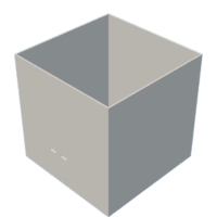
Use a laser cutter to cut the acrylic according to the attached patterns. The holes in the lid are for the plant, photoresistor, and DHT11. The finished acrylic box with the 3D printed inner box is pictured above.


Step 5: Construct Holder Pieces for DHT11 and Photoresistor


3D print the two pieces attached below. The circular one will be glued beneath the hole for the photoresistor and the square one will be glued below the hole for the DHT11.


Step 6: Drill Hole for Power Cord

Drill a hole in one side of the acrylic to fit power chord for the Arduino.
Step 7: Complete Construction


Once all wires are soldered and the components are made, cut wires to an appropriate length. Glue each RGB LED Light to one side of the inside of the acrylic box. Each solder joint between wires should be taped with electric tape to avoid them from touching. Tweezers are extremely useful in this process. Glue the top of the inner box to the bottom of the acrylic lid. Next, tape the soldered protoboard and Arduino to one side of the inner box. Finally, carefully put the inner box into the outer box with all wires attached and glue the edge of the lid to the top of the outer box with hot glue. Photos of this process are pictured above.


Comments
7 days ago
Nice job on this project!