
Introduction: "The Whimsy Artist" - a Creative and Destructive Robot


Welcome to the wacky and whimsical world of "The Whimsy Artist"! In this extraordinary tutorial, we'll embark on a thrilling adventure to create a robot that channels the soul of an artist. Inspired by the wild emotions and unpredictable reactions of real artists, our robot combines the joy of creation with the fury of destruction. When it's in its creative zone, it sculpts and shapes unique geometries based on the code. But beware! If anyone dares interrupt its artistic flow, it transforms into a raging force ready to obliterate its path. Get ready for a journey that blends artistry and robotics in the most whimsical way possible. Let's dive in and unleash our inner whimsy!
(This project was developed by Laura Marsillo, Aysima Yavuz and Yagmur Bulut as part of the Computational Design and Digital Fabrication Seminar in the Master's programme Integrative Technologies and Architectural Design Research (ITECH) at the University of Stuttgart)

Supplies


Electronics
- Arduino Uno
- Breadboard (85mm x 55 mm)
- USB micro to USB data transfer cable
- Motor driver
- Main bodied with Two DC motors
- Ultrasonic Distance Sensor
- IR distance sensor (2)
- Servo motors (2)
- Jumper wires
- 9V battery
- 1.5 V battery (4)
Materials
- Double sided tape
- Glue
- PLA
- Brush
- Salt
Tools
- Soldering iron
- Scissors
- Pliers
- Ruler
- screwdriver
- 3D printer
Attached are the 3D files for the 3D printed part


Step 1: Assembling the Robot

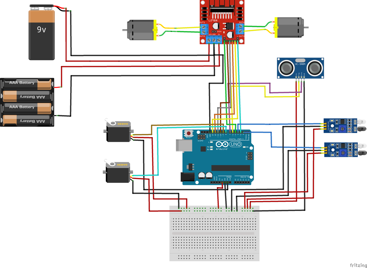


Begin by assembling the robot chassis and attaching the motors and wheels.
Ensure the proper operation of "The Whimsy Artist" by connecting it to a reliable power source.
Connect a set of batteries to supply the necessary power. Connect the positive (+) terminal of the power source to the 5V pin on the Arduino board and the negative (-) terminal to the GND pin.
Connect the motor driver module to the Arduino board, and wire the motors to the following motor control pins:
Left motor:
Enable pin: [enLeft] (connect to Arduino pin 5)
Forward pin: [leftForward] (connect to Arduino pin 10)
Backward pin: [leftBackward] (connect to Arduino pin 11)
Right motor:
Enable pin: [enRight] (connect to Arduino pin 3)
Forward pin: [rightForward] (connect to Arduino pin 12)
Backward pin: [rightBackward] (connect to Arduino pin 13)
Mount the IR distance sensor module at the front of the robot and connect the sensors to the following pins:
Left sensor: [IRLeft] (connect to Arduino pin 4)
Right sensor: [IRRight] (connect to Arduino pin 2)
Position the ultrasonic sensor facing forward and connect it to the Arduino board as follows:
Echo pin: [Echo] (connect to Arduino pin 7)
Trig pin: [trig] (connect to Arduino pin 6)
Attach the servo motors to the robot chassis and connect them to the Arduino board:
Servo 1:
Signal pin: [pos1] (connect to Arduino pin 9)
Servo 2:
Signal pin: [pos2] (connect to Arduino pin 8)
Attachments
Step 2: Code Explanation


Now, let's delve into the intricate details of "The Whimsy Artist" code. The code is divided into two main stages: the creative and happy mode and the destruction and angry mode. Here's a breakdown of the code execution in each mode:
a. Setup Phase:
In the setup phase, the necessary pins and sensors are initialized, servos are attached, and the line detection sensor is set up. This ensures that all the required components are ready for operation. After the initialization, the robot enters a waiting state for 10 seconds, allowing time for preparation and adjustment.
b. Loop Phase:
Once the setup phase is complete, the robot enters the loop phase, where it continuously executes the code to create and destroy artistic patterns.
i. Distance Measurement:
At the beginning of each loop iteration, the robot measures the distance using an ultrasonic sensor. This sensor calculates the distance between the robot and any obstacle in its path. Based on this distance, the robot determines whether it is in the presence of an object or in an open space.
ii. Creative and Happy Mode:
If the measured distance is greater than 50cm and no object has been detected, the robot enters the creative and happy mode. In this mode, the robot showcases its artistic capabilities through a mesmerizing spiral motion. It adjusts the speed of its wheels, opens the dispenser, and moves in a spiral pattern, allowing the creation of unique and captivating artistic expressions.
iii. Object Detection and Angry Mode:
If the measured distance is less than or equal to 50cm, the robot stops, closes the dispenser, and rotates 180 degrees. This indicates that an object has been detected, interrupting its creative flow. The robot then transitions into the angry and destructive mode, symbolizing the frustration experienced by artists when their creative process is disrupted. It sets a flag to indicate the presence of an object.
iv. Line Following Function:
In the angry and destructive mode, the robot enters the line following function. It reads the line detection sensor to navigate its path. Additionally, it sweeps the second servo from 0 to 180 degrees, mimicking the brushing movement of an artist's hand. Depending on the detected color (black or white), the robot decides whether to turn right or left, following the path accordingly.
By combining these two stages, "The Whimsy Artist" creates a dynamic and immersive experience that emulates the emotional journey of an artist. From the joyful creation to the fiery destruction, this robot encapsulates the essence of artistic expression and resilience.
Now that you have gained a deeper understanding of the code, you can further explore and modify it to unleash your artistic vision and unique robotic interactions.
Attachments
Step 3: Testing the Sensors and Motors


Power up the robot and place it on a surface suitable for drawing. When the robot enters its creative mode, observe how it defines different geometries based on the code.
  //--------------------------------//NO OBJECT_ SPIRAL MOVIMENT
  } else { // spiral movement

    Serial.println("Spiral movement");
    delay(2000); // add a delay of 2 second before starting the spiral movement


        //Move Forward
    analogWrite(enLeft, 150);
    analogWrite(enRight, 150);
    digitalWrite(leftForward , LOW);
    digitalWrite(leftBackward, HIGH);
    digitalWrite(rightForward, HIGH);
    digitalWrite(rightBackward, LOW);
    delay(1000);


    //TURN RIGHT
    analogWrite(enLeft, 100);
    analogWrite(enRight, 200);
    digitalWrite(leftForward , LOW);
    digitalWrite(leftBackward, HIGH);
    digitalWrite(rightBackward, LOW);
    digitalWrite(rightForward, HIGH);
    //servo.write(0);    //---------------------------------------------------- OPEN DISPENSER
    delay(1000);


    //TURN LEFT
    analogWrite(enLeft, 200);
    analogWrite(enRight, 100);
    digitalWrite(leftForward , LOW);
    digitalWrite(leftBackward, HIGH);
    digitalWrite(rightBackward, LOW);
    digitalWrite(rightForward, HIGH);
    delay(1000);

  }
However, be prepared for its reaction if you interrupt its creative flow. It will become angry and return to destroy its path.
//--------------------------------------------DETECT OBJECT
  if (Ceni <= A) {  // obstacle detected
    Serial.println("Obstacle detected");


    //-------------------------------------STOP
    Serial.print("stop");
    analogWrite(enLeft, 70);
    analogWrite(enRight, 70);
    digitalWrite(leftForward , LOW);
    digitalWrite(leftBackward, LOW);
    digitalWrite(rightBackward, LOW);
    digitalWrite(rightForward, LOW);


    // -----------------------------------CLOSE DISPENSER


    servo.write(200);
    //servo.detach();
    delay(1000);


    // -----------------------------------ROTATION
    int rotations = 0;
    while (rotations < 1) {  // make one 180 degree turn
      //turn 180
      Serial.print("TURN");
      analogWrite(enLeft, 150);
      analogWrite(enRight, 150);
      digitalWrite(leftForward , HIGH);
      digitalWrite(leftBackward, LOW);
      digitalWrite(rightForward, HIGH);
      digitalWrite(rightBackward, LOW);
      delay(2000);


      //-------------------------------------STOP


      Serial.print("STOP");
      analogWrite(enLeft, 0);
      analogWrite(enRight, 0);
      digitalWrite(leftForward , LOW);
      digitalWrite(leftBackward, LOW);
      digitalWrite(rightBackward, LOW);
      digitalWrite(rightForward, LOW);


      //delay(2000); // wait for the robot to stop before starting the next turn
      rotations++;


    //delay(1000); // delay after the 180-degree turn
    objectDetected = true; // set flag to true


    }

// If an object has been detected and avoided, resume line following


  if (objectDetected && Ceni > A) {
    objectDetected = false; // reset flag
    lineDetection(); // resume line following
    }
 }
To "destroy" its path, a linefollowing function is created, where it will follow a White line.
// If an object has been detected and avoided, resume line following


  if (objectDetected && Ceni > A) {
    objectDetected = false; // reset flag
    lineDetection(); // resume line following
    }
 }
//----------------------FUNCTION - LINE DETECTOR
void lineDetection() {


  while (true) {
      readingL = digitalRead(IRLeft);
      readingR = digitalRead(IRRight);

      Serial.print("IRLeft : ");
      Serial.println(readingL);
      Serial.print(" IRRight : ");
      Serial.println(readingR);


  // ---------------------------------------MOTOR SERVO 2-------------sweep the second servo from 0 to 180 degrees in steps
    for (int pos = 0; pos <= 180; pos += 1) {
      // tell servo to go to position in variable 'pos'
      servo_2.write(pos);
  //-------------- wait for 15 milliseconds for servo to reach the position
      delay(2);
    }


     if(readingL==1 && readingR==1){
        //IRLeft and IRRight are 1 ; both are on Black
        //Move Forward
       analogWrite(enLeft, 120);
       analogWrite(enRight, 100);
       digitalWrite(leftForward , LOW);
       digitalWrite(leftBackward, HIGH);
       digitalWrite(rightForward, HIGH);
       digitalWrite(rightBackward, LOW);


      }
        //0 means output of IR sensor is high as the sensor is on white surface
      else if(readingL==0 && readingR==1){
        //IRLeft and IRRight are 0,1 ; IRLeft is on White
        //turn left
        analogWrite(enLeft, 120);
        analogWrite(enRight, 80);
        digitalWrite(leftForward , LOW);
        digitalWrite(leftBackward, HIGH);
        digitalWrite(rightForward, HIGH);
        digitalWrite(rightBackward, LOW);
      }


      if(readingL==1 && readingR==0){
        //IRLeft and IRRight are 1,0 ; IRRight is on White
        //turn right
        analogWrite(enLeft, 80);
        analogWrite(enRight, 120);
        digitalWrite(leftForward , LOW);
        digitalWrite(leftBackward, HIGH);
        digitalWrite(rightForward, HIGH);
        digitalWrite(rightBackward, LOW);
      }


       else if(readingL==0 && readingR==0){
        //IRLeft and IRRight are 0,0 ; IRLeft and IRRight are on White
        //Stop
        analogWrite(enLeft, 0);
        analogWrite(enRight, 0);
        digitalWrite(leftForward , LOW);
        digitalWrite(leftBackward, LOW);
        digitalWrite(rightBackward, LOW);
        digitalWrite(rightForward, LOW);


    }
  }
}
Step 4: Fine-tuning the Parameters


To further personalize "The Whimsy Artist," you can experiment with the code to define different geometries or patterns for its creative mode.
Adjust the parameters to change its behavior and the intensity of its destructive mode. This allows you to tailor the robot's artistic temperament to your liking.
Step 5: Embracing the Whimsy


"The Whimsy Artist" represents the fusion of art and technology. Embrace the whimsical nature of this project and let your imagination run wild. Consider adding additional features such as colorful LEDs, sound effects, or even integrating it with a computer program to create interactive art installations. Unleash your creativity and explore the limitless possibilities.


Comments