
Introduction: Make a Drill Press Vise Without Welding


This time I will show you how to make a very simple, but at the same time very sturdy and rigid - metal drill press vise without welding.
How I did it - you can check by looking DIY video or you can follow up instructions below.
For this project you will need:
Materials:
Mild Steel U-Shaped Metal Beam ( I used 14cm in width by 6cm in height)
Angle iron 25x25mm
M12, M10 Allen bolts
M20 threaded rod
M12 stainless steel round stock
Tools:
Angle grinder with cutting and grinding discs
Drill press (or just a regular drill) with bits for drill 10mm, 12mm, 20mm, and 38mm holes in metal
M10, M12 and M20 taps
Allen wrench
A rotary tool with cutting discs
Permanent marker, ruler, and sharp scraper for marking
Step 1: The Main Stock


I started with this Mild Steel U Shaped Metal Beam leftover. It is 14 centimeters in width and 6 centimeters in height. Measured and cut 26 centimeters, which will be the total length of the vise. That fallen off-cut will be used later - because I want to squeeze as much as possible from this single piece.
Step 2: More Cutting


Next, trimmed both sides to lower it from 6 centimeters to 2.5 centimeters in height.
To get a perfectly straight and leveled cut I used this homemade attachment for the angle grinder. A few bearings, bolts, and square tube convert this angle grinder into a rolling cutting machine. Of course, those cuts could be made by hand, but I wanted to try this jig in this build and it performed extremely well. A single cut left a very nice and perfectly straight edge.
Step 3: Slot in the Middle


I drilled two 38 millimeters holes in both ends and with an angle grinder connected those to form a nice 38mm slot.
Step 4: Finished Bottom Part


On both sides, I marked, drilled, and tapped M10 holes. Here I want to make the vise a bit wider. I used a 25 by 25 millimeters angle iron piece with drilled representing holes. This will extend the vise bottom which mostly will be used as a clamping surface. A bit of grinding was needed to make the whole surface perfectly flat.
The very last modification on this base was to drill and tap 4 holes in corners for M12 Allen bolts.
Step 5: Making Vise Jaws


Did you remember that off-cut? I will use it and cut a pair of angle iron pieces for the vise jaws. It not only helped to get the best use of the U-shaped metal beam, but it has a very nice shape also. The bottom part is thicker than the vertical one, which I like a lot. I managed to get only two pieces from that leftover so the third one I cut from a regular angle iron found in my metal scrap. Here you could see the angle iron shape differences.
Step 6: Working on Jaws


Two angle iron pieces placed at the base ends will be secured permanently, while the middle one should move freely. The process here is the same as in all connection points in this build - drilling a pair of holes in each part to secure with M12 Allen bolts.
This angle iron is way too thin for my planned application, so I’ll make it thicker by adding this 10mm of thickness flat steel strip. As the inner corner has some radius I need to trim that steel strip bottom respectively to get the perfect fit.
Angle iron was a drill and tapped to make mounting points for that reinforcing steel strip. A pair of M10 Allen bolts secured them to one solid piece.
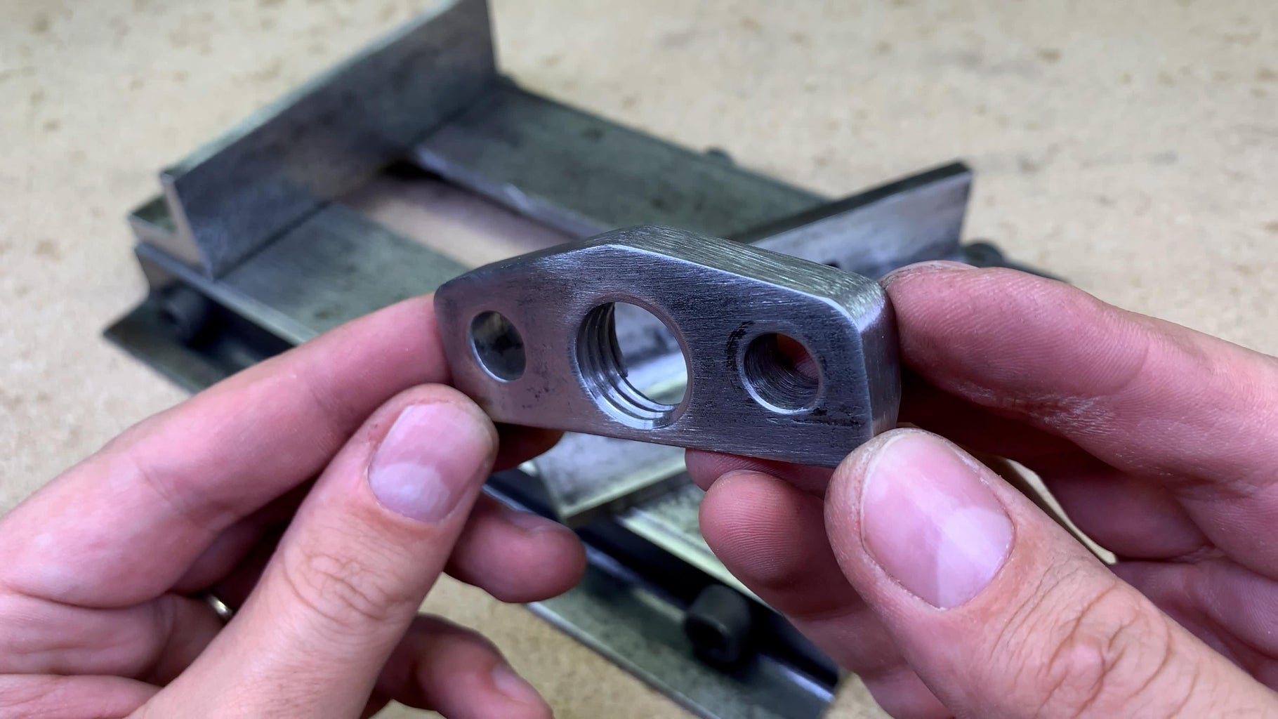
Step 7: A Hole for Main Vise Screw


Here is the answer to why such thickness was needed. In this palace, I will use an M20 threaded rod as the main vise screw.
This is a good example of how to drill holes in strangely shaped metal parts without a drill press vise. A simple support piece made of scrap wood and a clamp - did the job.
After tapping it is hard to tell that all this thickness was achieved by sandwiching two metal pieces together. By looking at the thread - It looks like one solid piece.
Step 8: Permanent Parts Fixed in Place


As I like to make stuff not only functional but at the same time look neat - I modified both sandwiched parts to a more lightweight and aesthetic look. The smaller part gave the idea of how the angle iron should be trimmed too.
And now both parts could be fixed permanently.
Step 9: Mounting Sliding Jaw


To keep the sliding jaw moving freely along the slot I will sandwich it with those two metal pieces. After drilling and tapping, all parts could be bolted together. And it slides way better than I expected.
Step 10: The Main Screw


To keep moving the sliding jaw I use an M20 threaded rod. Here I have to pay the price of using that nice shape-angle iron jaw. The bottom part is too thick for the M20 threaded rod. I marked and grinded the needed groove with the rotary tool.
It took a while, but now the threaded rod fits perfectly.
Step 11: Modifying the Main Screw


To attach the threaded rod to the moving jaw, but at the same time let him spin freely - I use those two metal strips. First I marked and grinded a groove on the rod with the angle grinder. Later on, I made a different size U shape cut in the etch metal strip. Here Is how it works. The part with a bigger slot will act as a spacer between the jaw and the end of the rod. The piece with a smaller slot will hold a threaded rod attached to the moving jaw and also let the rod turn freely. When the holes were drilled and parts mounted on the sliding jaw I didn't like how it looked, so made small corrections. This time I modified only those two parts. I wanted to shape them in the same form at one time, so I bolted them together with a pair of Allen bolts while cutting and grinding them to the needed shape. It looks way better than before.
Step 12: Working on Handle


Before attaching a threaded rod to the vise I need to mount a handle. The perfect candidate is this 12mm diameter stainless steel rod. To join them together some drilling and grinding were needed. The threaded rod got a hole and a slot in the middle. Meanwhile, the stainless steel handle was shaped to fit in that slot. To keep two parts together I use a pin made from a nail and flatten another nail end. Holds in place and the handle moves freely.
Step 13: Final Assembly


Time to mount it into the vise.
Step 14: Some Testing and Insights


It spins very freely. Let’s try it out on a drill press.
This vise has enough holding power to hold not only square parts. The metal strip or round pipe makes no issue too. What I like a lot - is that this vise is low profile, wide, and quite heavy and it could be used for all kinds of applications around the workshop. For example, I cut this metal strip without clamping the vise onto the workbench. During the cut, the vise moved just a hair, which saves me time instead of clamping it.
Yes yes yes I’m hearing you shouting - why make such a thing if you could buy it for a decent price? Well, the reason is the same as with all other homemade tools - you use what you have, make it to fit your specific needs (including shape, size, and technical characteristics) and what is most important - enjoy building it.

Grand Prize in the
Metal Contest


25 Comments
4 months ago
Very good Instructable.
I have several regular metal vices I've inherited over the years but they have a serious problem: their maximum jaw openings are too small to be of any practical use for a lot of my projects (in wood, metal, glass and ceramic) on my drill press. This Instructable appears to be easily scalable to a usable maximum jaw opening size.
I have the tools, I have the skills, now to just find the time to enjoy the build.
4 months ago
Cheap DP vises are available, but making it yourself is so much more fun! Thanks!
4 months ago
Love it, just one question: Where do you source the steel? That's not something you find at Home Depot.
Reply 4 months ago
While I'm not the author, I have a few suggestions: While you can get smaller pieces on line from McMaster, many "metal warehouse" type places, and even ebay, shipping can be expensive unless the pieces will fit in a flat rate box from the PO. (McMaster can be cheaper if you are close to one of their warehouses). Depending on where you live, there might be metal suppliers within driving range, or even better, a local fabricator with a scrap pile you could befriend. Even estate/yard sales; dirt cheap, but a total roll of the dice!
4 months ago on Step 14
When drilling round stock use a poor man’s v blocks. That is 2 pieces of pipe bolted together. They will work just like a v block for drilling and are cheap to make. Clamp them between some boards or metal when you drill them for the bolts so the holes and pipes are straight.
4 months ago
1) Any chance of an Instructable for the angle grinder rollerjig ?
2) Did you consider slots in the base flanges to bolt it down under a pillar drill or milling machine ?
7 months ago on Step 8
I would probably build of these myself, but I am one of those metric-avoiding retro (i.e. American) types, and it is too time-consuming to re-scale all of the dimensions to be able to use materials commonly available here.
Reply 4 months ago
Those were my first thoughts, too.
Excellent Instructable.
5 months ago
Congratulations. Well laid out project. Totally agree on use what you've got policy!
5 months ago
Congratulations on winning the Grand Prize in the Metal Contest! This was our favorite finalist by far. And we loved that you wrote,"...you use what you have, make it to fit your specific needs (including shape, size, and technical characteristics) and what is most important - enjoy building it." This is a beautiful example of practical ingenuity. Well done!
6 months ago
Nicely done. I love the way you put the efforts in the finition, all the angles and the rounded corners. Also the grinder jig, love it. Thanks for sharing that good tutorial.
6 months ago
beautiful, good work
7 months ago
What a great project.
7 months ago
Really enjoyed
7 months ago
Very nice pictures
7 months ago on Step 14
Repurposing and building for form and function is a great way to spend time in the shop with my teenage son.He is all about buying things already made. And when all the fabulous creations out there being shared, he is now understanding that crafting, imagination,doing and time, equals satisfaction and a sense of pride. He and I are inspired by folks such as yourself who like to show the How To aspect of these ideas.
We especially liked the the clever setup with the angle grinder jig for straight cuts.
Great pieces of work! Thanks for sharing.
7 months ago
Beautiful job. I am in awe of your control of the angle grinder cutter.
7 months ago
i mean, yeah, you can buy a drill press vice for pretty cheap. but thats a really nice build eother way!
7 months ago
It's beautiful! How did you finish the metal? (Any chunk of metal from my basement is going to be at least a bit rusty.)
7 months ago on Step 2
The angle grinder cutoff sled is brilliant.