
Introduction: Android Robot Head Hardware


This Instructable describes how to build an android head. It uses an Arduino Nano as a servo controller.
When I visited an exhibition of robots at our local museum, one of the most popular exhibits was a robot head that tracked people's faces and tried to copy their expressions (maybe this one). I wondered how it worked and whether I could do something similar.
When you build a humanoid robot head, it's hard to know where to start. I looked at other examples and couldn't work out how their chassis was built or how the actuators were attached. Most use hobby servos which directly drive the facial features or use Bowden cables. Mostly with robots, we're building in a "engineering" style rather than an "organic" style; with an android, you have to merge the two..
The head has six actuators
- move head left/right
- move head up/down
- move eyes left/right
- move eyes up/down
- move eyebrows up/down
- move jaw open/closed
There's quite a lot of space left in the skull which I used for the electronics. Animatronic heads might use the space for actuators to
- turn eyebrows angry/sad
- move eyebrows individually
- eyelids
- lips smile/sad
- tilt head
A future Instructable will describe how to use an ESP32cam to control the robot head (via the Nano) and do face detection.
Step 1: Robot Head Chassis


As I say, it's hard to know where to start. I decided to go for a metal "spaceframe". I chose 8mm microbore copper central heating pipe. It's easy to work with and fairly cheap (around £3 for what I used).
I printed some elevations of a human skull at around the right size and bent the pipe to fit. It's hard to bend pipes "freehand" without them kinking. I found it easiest to bend them around the different-sized pulleys of a stand-drill. A range of tin-cans would work too.
The pipes soft-solder easily using a blowtorch. I've also got a huge vintage plumber's soldering iron which works beautifully but they're hard to find. A small electricians soldering iron doesn't have the thermal capacity to work with this much copper.
The "bone" part of the skull is made from air-drying clay. You can see in the photo how I used a layer of cardboard to provide an initial form to the "bone" then added thin layers of "clay" to make a sandwich. It was easier than I expected and quite satisfying to do.
The "clay" sticks well to the copper pipe (you can paint PVA glue onto the metal if it doesn't want to). If you make a mistake, you can carve bits off or add bits on. For modelling, I mostly just used my fingers although I needed tools for the teeth. There are various recipes for DIY "clay" but it's a lot less bother to just buy it - and it works better too.
I found this isn't a project where you can design something then build it. I was always asking myself "where will that fit?" and "how will this work?". So you design it as you go along.
Step 2: Servos and Camera


The servos are mostly held in place by copper wire taken from cable for ring-mains. It's easy to solder onto the copper pipes although sometimes you might want to drill a hole in the pipe first. Copper wire is easy to bend to get the servos just where you want them. Copper wire is too soft for servo push/pull rods; any steel wire would do but I use MIG welder wire - it's steel covered in copper and so can be soldered. Search eBay for "MIG welder wire" It's hard to get small quantities of it - see if your local welding hire shop has the tail end of a reel. It's worth having for projects.
There are four micro-servos in the head
- move eyes up/down
- move eyes left/right
- move eyebrows up/down
- move jaw open/closed
And one standard servo
- move head up/down
In the base there's one micro-servo
- move head left/right
I chose a standard servo for the head up/down as the head is quite heavy. It's screwed onto a simple aluminium bracket which is embedded in the bone. To embed it, I just held the bracket against the inside of the skull and covered it in more "clay".
The head rotates on a long bolt which forms the neck. I glued a piece of the copper tube over the bolt then soldered wire onto it. The wire bends around the bottom-most tube to form a hinge. That allows the head to tilt up/down and turn left/right. For the wire, I used TIG welding rods (Tungsten Inert Gas welding) . The rods are mild steel wire covered in copper and can be bought cheaply on eBay. It's as strong as steel but can be soldered because it's covered in copper. As you can tell, I'm a fan of soft-soldering: it's quick and easy. Search eBay for "TIG welding rods". Once again, it's worth having some in stock for other projects. (Maybe galvanised steel wire would work but I find it hard to solder.)
The neck bolt passes through two ball bearings which are a press-fit into the wood of the box. I covered the bolt in "clay" vertebrae to make it look more neck-like.
The servo for head left/right is in a wooden box under the head. I initially used a crank and a push-rod but found that the backlash was too big. The servo now sits directly under the neck shaft. The servo horn has been enlarged by encasing it in polymorph.
The camera is a slight afterthought. I'd originally planned to use a Raspberry Pi and PiCam. The PiCam is quite small (25x24mm) and fits neatly behind the nose-hole. I got face detection working on the Pi but having to deal with Linux gives me a pain in the stomach. So I gladly changed to the ESP32cam. The ESP32cam is bigger (27x40mm) but a bit of carving made space for it.
Step 3: The Eyes


I got some eyes out of a toy from a car-boot sale and mounted them in a wire frame. You can see in the test-rig how micro-servos move them up/down and left/right.
Each eyeball has holes drilled in the top and bottom so a brass wire can form a vertical pivot-axle. A spring holds the pivot in place. A servo moves them left/right. In the photo, the push rods go into holes drilled in the eyeball but that turned out to be unreliable - the rods would jump out or jam. So I replaced the holes with small wire "eye-bolts" which work far better.
Each pivot-axle is soldered onto a horizontal shaft that allows the eyes to rotate up/down. Its axis of rotation passes through the centres of the eyeballs.
There's a third micro-servo to move the eyebrows. I puzzled for a while about what the eyebrows should look like then remembered the cool eyebrows on the Sutton Hoo helmet. Everything about the Sutton Hoo helmet is cool.
The eyebrows are made by wrapping wire around a tapering former. I used a tapered reamer but a pair of scissors might work better - the eyebrows wouldn't be so fat. I used MIG welder wire because I have lots of it. I think copper wire would be have been better or the (aluminium) florists' wire that comes in nice colours.
Step 4: Controlling the Servos

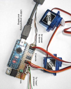


The servos are controlled by an Arduino Nano used as a dedicated servo-controller. I did it like that because I think it's the easiest way to get a Raspberry Pi or ESP32cam to control servos. A Pi can drive lots of servos (in a poor-quality jittery way using software) but an ESP32cam can't. So in this project, the ESP32cam will do face detection and send commands to an Arduino Nano which controllers the servos.
The ESP32cam has very few pins exposed. In most projects it's used just as a Wi-Fi camera but the ESP32cam is capable of much more than that. I discuss the situation further in my Instructable on a simple robot arm.
A Nano has a big advantage over a dedicated pwm servo driver chip like the PCA9685: it can control the servos much more intelligently.
When you send a command to a servo, you're telling it where to go. A standard servo goes there as fast as it can. If it's driving a load with a lot of inertia - like turning the head in this project - that can require a large torque which might damage the servo gears. When you try to stop the head turning, it could well overshoot leading to oscillation.
A second problem comes when you have several servos. You often want them to act together. You want them all to arrive at their targets at the same time. In this project, you might want the head to turn to the right and up while the eyes compensate by turning to the left and down. If the head is still, you will want the eyes to dart around. And the jaw and eyebrows aren't affected by the head motion at all so servos are assigned to groups. You can see the servos acting together or independently in this video.
I discuss how that is done in my Instructable on servo driver software. It also describes the comms protocol I use. The Arduino code is available in that Instructable.
For testing, I used my servo sequencer described in this Instructable.
How should the ESP32cam talk to the Nano? In my simple robot arm project I wanted data to flow back and forth between the Nano and the ESP32cam. So that Instructable describes a complicated 4-wire protocol. In this project data only flows to the Nano so I'm using a serial line.
The ESP32 has two UARTs but in the ESP32cam the pins for only one of them are exposed. That single UART is used for programming but I also want to use it for data.
In the Nano, the Nano's UART is connected to a USB-to-serial convertor chip (usually a CH340) via 1k resistors. The 1k resistors mean that the ESP32cam can override the signal from the USB-to-serial convertor. When you're programming the Nano you must disconnect it from the ESP32cam.
When you program the ESP32cam, the Nano will see the programming commands on the serial line so, again, you should disconnect them.
I built the circuit on a small piece of stripboard. It's such a simple circuit it's not worth having a PCB manufactured. It's nice having all the electronics inside the skull - you need much fewer cables going into the base.
Step 5: Conclusion

Before I started I studied a lot of other heads to try to understand how other people approached the problem.
After I'd built the head I had a lot more respect for other people who've built heads. It's not obvious how to do it or how to connect up the mechanics. I'm impressed by how much people manage to fit in.
So what have I learned? The "space frame" design is a good way to make a head. Other people use an internal chassis. With a chassis, you have to work out how to hang the "skin" on the outside. With a space frame, you have to work out how to attach the servos. I guess both are equally tricky.
Air-drying clay is very nice to work with - I used DAS. I can see why so many people like it. I can't think of a better alternative for curvy biological shapes. Fimo would also be good but harder to work with for large pieces. I guess one could download a 3D-printable head and hack it to take servos but I think 3D-printing is for when you already know what you're doing.
This Instructable describes the hardware of the robot head. I’ll publish an Instructable about how to use an ESP32cam do face detection and control the head via the Nano as soon as I’ve finished the software.

First Prize in the
Make it Move Challenge


3 Comments
5 months ago
This is insanely cool!!
Reply 5 months ago
Thanks. Yes it does look cool and will be even more so when I finally get the software working. Imagine if it looks you in the eye and follows you round the room! Unfortunately I have some Real Paid Work to do so it will take a while.
Reply 5 months ago
Haha so true - work getting in the way :D