
Introduction: Make Your Own Customisable Desktop LED Neon Signs / Lights


Hello, I’m Lewis, and this is DIY Machines. A place where I get to show you step-by-step how to build 3D printable projects. Today we’re making some of these awesome customisable desktop neon signs.
Neon effect LED signs are popping up everywhere at the moment which is understandable, they look fantastic and are super easy to build at home. So I wanted to design and share some of my own
These ones can be powered by either a USB cable or 4 'AA' batteries giving you a lot of flexibility for placement. Why not use one to illuminate your next garden or beachside party?
They are also dimmable to help create the right level of ambience for any setting. Use it to help illuminate a room or dial it down for a more subtle addition to your decor.
As for customising? You can print the parts in any rigid filament colour, like the glow in the dark cactus which keeps going when the lights are out, a vibrant day glow planet or the two tone lush leaf printed with Metallic Emerald magicPLA which mixes blue and green for an interesting effect.
It’s your choice as well for the colour of Neon effect LED’s used. There are several ready designed Neon shapes you can choose from and I’ll be adding some more soon. And if your comfortable you can edit the design and create something totally unique either for yourself or as a thoughtfully made gift to someone else.
Step 1: Project Video
As with all my project I have also created a detailed project build video which you can watch above. Below I have also laid out step-by-step instructions with photos as well so you can follow along in your preferred way. 🙂
Step 2: Designing Your Own Shape - Video
Since publishing this original Intractable I have created an additional video explaining how to draw your own shapes in Fusion 360. (There is a free tier and it works on both Macs and Windows). Here is the video should you wish to design your won shape.
Step 3: BOM / Supplies
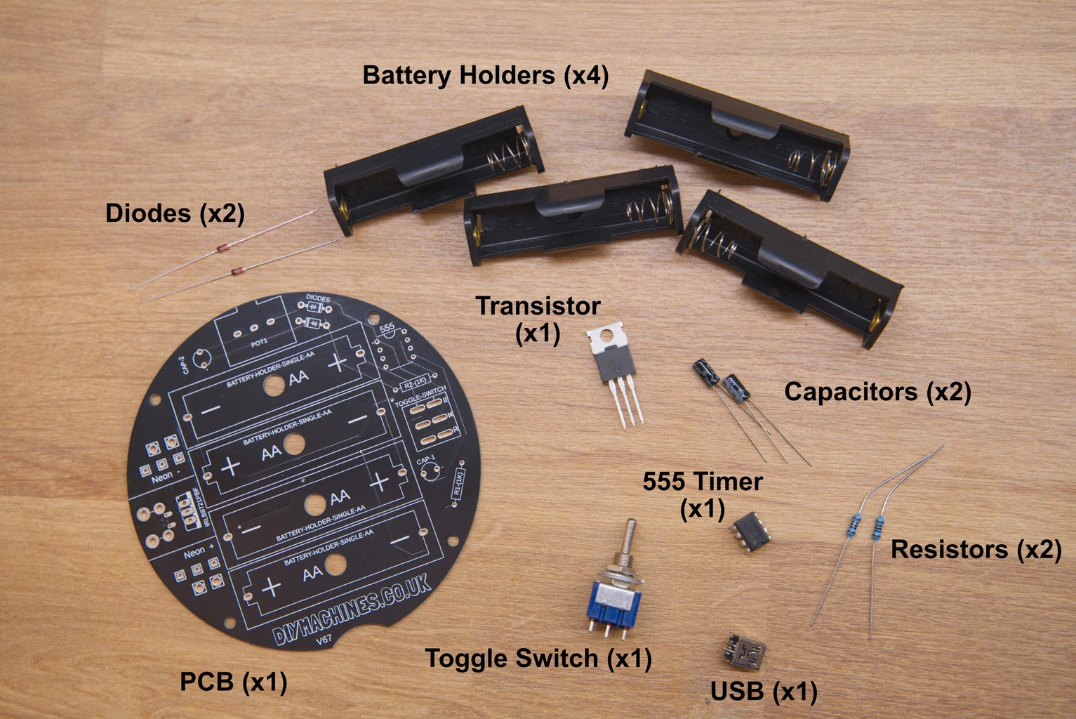


This is a simple build and can be printed and assembled in just a day or two. You will need a few things, you’ll find a full list below but briefly you’ll need:
- Neon effect LED strips: https://geni.us/NeonLEDStrip5v
- Resistors 1kΩ (x2): https://geni.us/Ufa2s
- Capacitors 0.1µF (x2): https://geni.us/Capacitor
- Switching Diodes IN4148 (x2): https://geni.us/IN4148-Diode
- Toggle Switch DPDT (x1): https://geni.us/DPDT-Toggle-Switch
- Female USB Socket (x1): https://geni.us/MiniUSBSocket
- 50k Rotary Potentiometer (x1): https://geni.us/Potentiometers
- 555 timer IC (x1): https://geni.us/555Timer
- MOSFET Transistor (IRLB8721PBF) (x1): https://geni.us/IRLB8721PBF
- Bolts (M3x8mm x6): https://geni.us/NutsAndBolts
- Electrical hook-up wire: https://geni.us/22AWGWire
- Filament: https://geni.us/3DJake (I used PLA)
- PCB: https://geni.us/DesktopNeonSigns
I designed the custom PCB with the help of PCBWay to make everything incredibly easy to assemble. You can follow the link above to buy one if you wanted to - it drastically cuts down on wiring and holds everything in just the right place.
Of course, if you don’t want to use the projects PCB then take a look at my wiring diagram above to build your own on a piece of perforated board or similar. 🙂
I’ve also put together a kit with everything you need except for the 3D printed parts which you’ll print yourself. Follow the links to my Etsy shop to find out more. Every kit sold helps fund the next project: https://www.etsy.com/uk/shop/DIYMachines
Step 4: 3D Printing Your Shape

For this step you will need:
- 3D Printing Filament - any rigid material such as PLA, PETG or ABS will do just fine.
So let’s start by printing the Neon Shape, there are several designs I’ve made which you can download. For your convenience I have attached several to this step (and I'll continue to do so with the printed parts on each of the relevant steps).
Attached are the Pineapple, Cactus and Planet designs.
These three are just a few and I’ll be adding more designs as time goes (you'll find additional shapes here). We’ll make the pineapple together in this video but the steps are nearly identical for all the others.
I printed my shape in 3D Jakes Ultra-Satin Gold PLA. It has a very cool glisten to it which will go nicely with the prestige pineapples once represented. No brim was required.
Attachments


Step 5: Trimming LEDs


For this step you will need:
- LED Neon strips in your chosen colours
- Scissors
Once printed we can measure out our LEDs and cut them to size. I’m going to use a combination of yellow and green. I want my colour to change at the top of the pineapple fruit before the leaves start, so I’ll insert the yellow neon from the point of the expected colour change and then cut it at the bottom of the shape.
You should only cut the LED’s through the centre of the dark marks you can see through the side of the strip. This is in fact copper contact points. I cut mine with some standard scissors carefully trying to go through the centre of the dark mark.
We can then measure out the green for the leaves and then the remaining yellow in the same fashion.
Step 6: Attaching Wires to LEDs


For this step you will need:
- Scissors / Flush cutters
- 21 AWG wire / hookup wire or similar
- Soldering iron
Remove the strips from the shape so we can next attach a pair of wires to one end of each strip. It doesn’t matter which end. Now, before we do this, to gain better access to these copper pads use your scissors or flush cutters to remove some of the silicone sheathing.
For each LED strip, cut a pair of wires long enough to go from the end of where the strip is positioned in the printed shape, round the 3D print, and then continue at least 12cm further out the bottom. We will need this extra length to connect it the rest of the electronics later.
Tin one end of the wires by adding some solder, and tin the LEDs pads. This will make connecting the wires to the pads much simpler. The positive connection is the one furthest from the front of the LED’s so I attached red wire here and black to the negative. Again, this will help massively later on.
Once you have done this for all the LED strips for your design we can pop them back into the 3D printed pineapple shape. I started with the green so the wires could be routed beneath one of the yellow strips. You may route yours in a different order depending on your shape and number of colour changes you're employing.
Step 7: Printing the Housing


For this step you will need:
- Rigid 3D printing filament
- M3x8 Bolts (x2)
We can then 3D print the two parts of the base. Again I printed mine in Ultra Satin Gold PLA. I designed the base to be printed in two parts so that we don’t need to waste material or time on printing support structures.
Place the top of the base on the lower section, insert the shape on top whilst threading the LEDs power wire through the opening, and then use your first two M3x8mm bolts to secure the LED shape to all the other parts from below.
Attachments


Step 8: Circuit: 555 Timer


Now, as mentioned earlier you can use the PCB for this project, which is what I‘ll be using, or follow the alternative wiring diagram (also included above) to wire up your own circuit.
PCBWay kindly produced the PCB which I'm using for this project. You can order them from this projects page on their site here. They have a good deal for new customers and their shipping is rather quick. Often if I order on Monday morning I receive them by the weekend!
I have tried to label the PCB well so that it is clear where each component goes. Some of them may fit in more than one orientation and it doesn’t matter, others however need to be orientated correctly. But don’t worry, we’ll go through adding each of the components now.
We will work roughly from the shortest component through to the tallest so that we can rest the PCB on the table surface whilst soldering - you will still find a pair of helping hands useful.
First up is the 555 timer IC. On the PCB you will see a little semi circle marking showing the correct orientation which needs to match the marking on the chip. Simply insert the legs, turn over the PCB and solder on the reverse side.
Step 9: Circuit: USB Connector


After the 555 timer we will add our USB connector. I'm using a micro USB style connector.
This and all the other components live on the top side, so we can insert it, flip the board over and solder it into place.
The big holes are used to hold it firmly in place, whilst the five little pins are the data and power pins. We only need to receive power from the connector so only need to solder the two small pins with pads at the back of the component.
Step 10: Circuit: Resistors, Diodes, and Capacitors


Next we can insert six components and then solder them.
The resistors are added in their marked slots - orientation for these does not matter. Spread the legs open on the reverse to hold them in place for now.
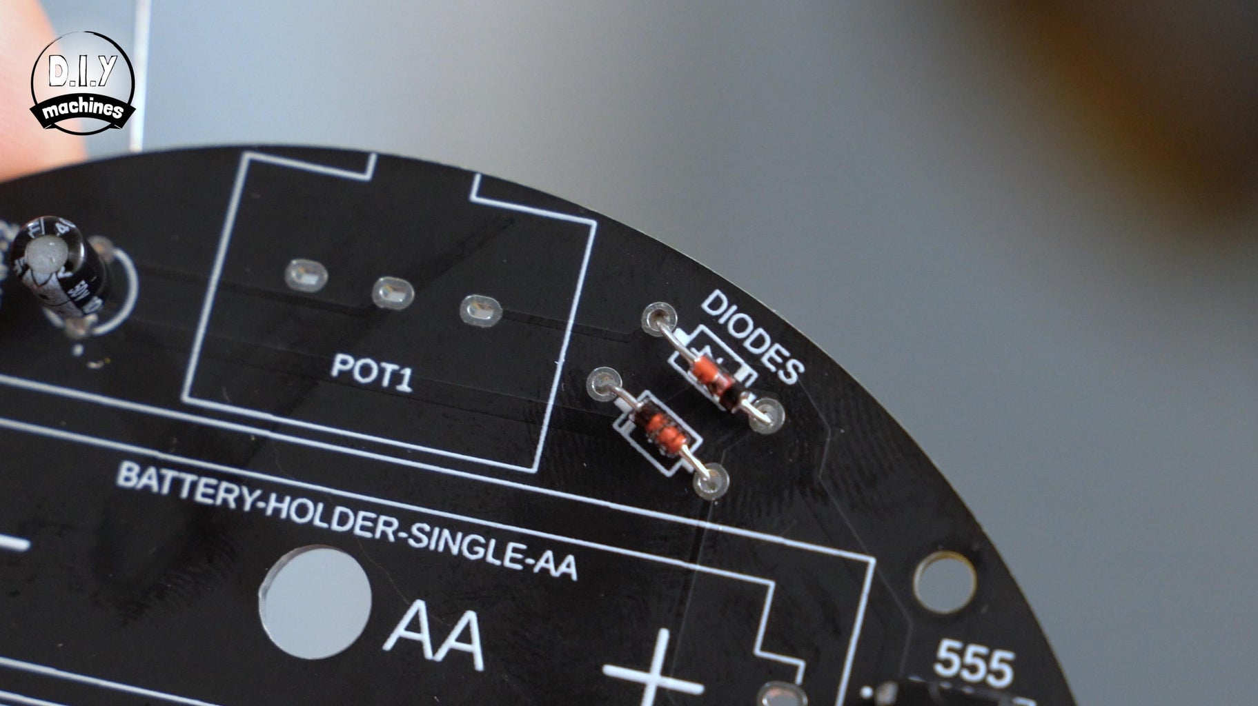
The capacitors and diodes need orientating correctly - the two capacitors have a white strip down one side and a shorter leg indicating the negative leg. The PCB has a small minus sign showing which side this should be on the PCB.
The two diodes have a black band at one end which should line up with the thick band indicated on the PCB.
Flip the board over and solder all six of these components before trimming their legs. Be sure to protect your eyes when trimming as the pieces of sharp metal can fly off at incredible speeds in any direction!
Step 11: Circuit: Battery Holder


Next up are the battery holders, the poles on the plastic housings need to match up with those marked on the PCB.
Solder these and trim the legs carefully again.
Step 12: Circuit: MOSFET Transistor


The transistors large metal back should be facing the batteries when inserted (as indicated by the thick white line on the PCB icon).
Flip, solder and trim.
Step 13: Circuit: Potentiometer


The potentiometers dial should be facing outwards when it is inserted.
Flip, solder and trim again. 🙂
Step 14: Circuit: Toggle Switch


The last component is the toggle switch which can be inserted in any orientation.
Flip over and solder whilst ensuring the switch remains installed perpendicular to the PCB (otherwise it may not properly align with the holes in the 3D printed enclosure).
Step 15: Circuit: LED Wires


We can now attach the wires we connected to the LED strips earlier to the PCB board.
It’s as simple as soldering all your positive wires to any of the through holes on the PCB in the group on the side marked as'Neon +' and all the negative wires to any of the five through holes grouped and labelled as 'Neon -'.
Again, as before, insert the wire on the top side and then solder them on the bottom side.
Step 16: Test the Circuit


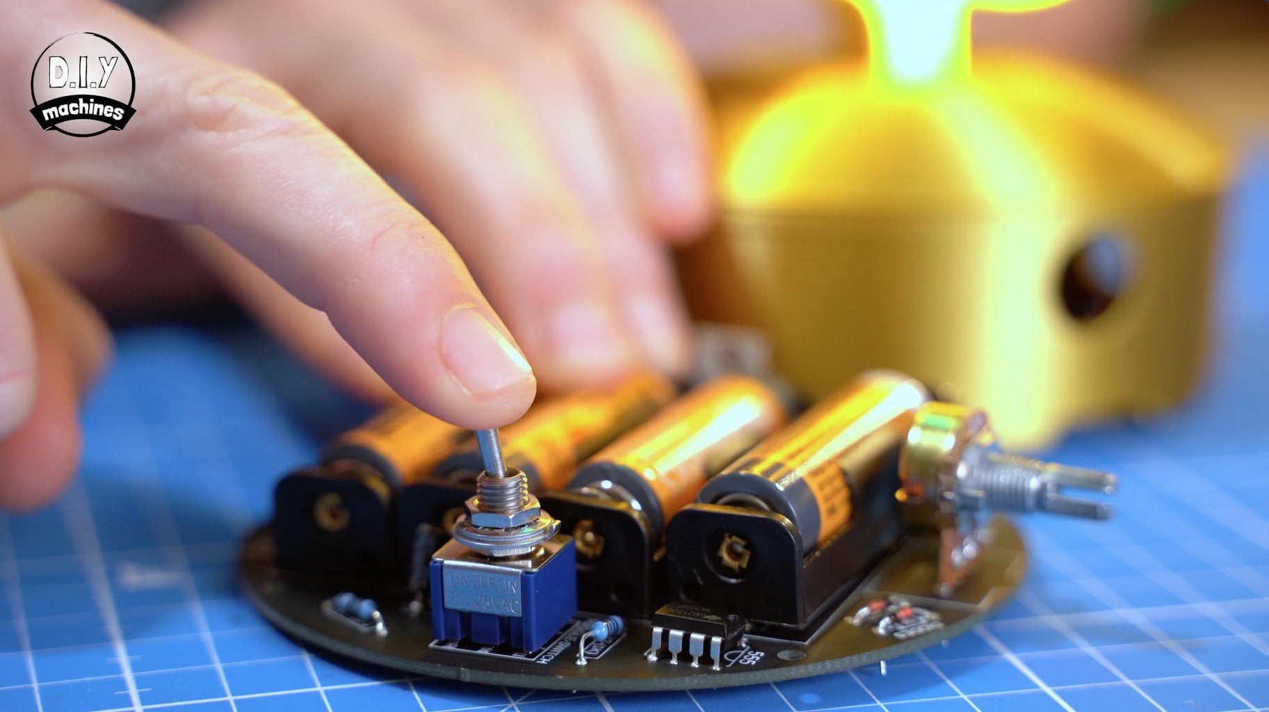
Let’s pop in some batteries or connect a USB cable to test everything before we prepare to secure the PCB in place.
The toggle switch has three positions. The central position is always off, pushing it away from the front will connect the batteries and pulling towards the front will connect the USB power. There is no need to worry about having batteries inserted and USB connected at the same time.
Step 17: Finish Off Enclosure


If it worked well for you we can 3D print the dial which is positioned on the end of the potentiometer before we fit the PCB into place. On the top of your project you’ll find to pill shape openings - one with a grid and one without. The transistor goes under the grid, the toggle switch into the open pill and the potentiometer thought the hole at the front.
Use your last four M3x8mm bolts to secure the PCB and then that’s project complete! :)
Great work.


Step 18: Project Complete

If you have enjoyed this project please consider subscribing and liking this Instructable - It helps me out a lot. You may also be interested in my Geoleaf project or giant hidden shelf edge clock.
Thank you so much for joining me to the end, until the next project, take care, do some good, and ciao for now! :D

First Prize in the
Lamps Challenge


49 Comments
10 days ago
1.) Do you have any information/tips/tutorials about how to use USB for power?
2.) The neon lights seem to be out of stock... any recommendations on an alternative?
Thank you!
Reply 7 days ago
(1) His design includes a mini-USB socket. So, you can simply use an old mini-USB cable and power plug.
(2) https://www.aliexpress.us/item/3256804003701329.html. Be sure to select 5V.
Question 7 days ago
Where do I find the .stl and .3mf for the foot of the neon (to import into Fusion 360))?
>>> I finally found it at https://www.printables.com/model/332454-how-to-mak...
named Neon Shape Starter.stp
Question 26 days ago
Hi, I am trying to create the cactus LED Light, but I do not know where to insert the wire from the LED Strip so it can go through the cactus to the housing top because there is a blockade. How do I go about this. Thank you
Question 5 weeks ago
I made a sample design but the heat from the LED strip disturbs the shape.
Any solution for that ?
Question 7 weeks ago
In your pineapple example, why not just wire the green and yellow together, end-to-end, instead of wiring them separately?
7 weeks ago
Wow! I wish i had that universal tool kit. Wonderful post.
Question 3 months ago
Very nice design and explanation! Thank you.
Could you show us how to make the designs. I'm hoping there's a simple approach in Autodesk Fusion 360.
5 months ago
Great project. I would love to see an explanation of the components. Why is there a555 timer?
Reply 4 months ago
The 555 timer is used for dimming the LEDs, with PWM that stands for Pulse Width Modulation. Maybe that video helps for understanding.
Reply 4 months ago
You pulse LEDs to dim them
4 months ago
Excellent tech project
4 months ago
Very nice project, I have ordered the PCBs from PCBWay and have found all the other components except for the battery holder. Do you have an amazon link(amazon preferable but anywhere) to the battery holder. Am planning on building several of these. Thanks.
Reply 4 months ago
I think I have found them on Aliexpress. Thanks again for the project
5 months ago
Excellent mixed tech project, documentation and video using non-arduino electronics. 555's are from my day (45 years ago, you know, old old school).
Reply 4 months ago
I will never not love a good ol' 555.
Reply 4 months ago
Right, I just fixed a simple LED dimmer with a 555, LM358 and a N-CH mosfet.
5 months ago
I'm so excited to try this! Thank you for such detailed and easy instructions! Great job!
5 months ago
Hi there - I'd like to have a go at this but don't have a 3d printer. Do you think it would work if I got a cheap battery enclosure from Amazon (if there is such a thing) and then attached the led strip to a backboard of some kind. It shouldn't produce heat so I was thinking maybe cable ties through a thin piece of wood or thick wire to hold it in shape. Just wondering how hard it would be to shape and if you think that would work?
5 months ago
I hope this is considered constructive critisism and not just having a go at you.
By having the batteries hidden away like that the design is not very user friendly, as you have to dismantle it to change them.
A better option if using batteries would be to have the batteries on the other side of the pcb so that they can be changed with less hassle and a standard battery compartment.
Or to include a transformer and charging circuit, so that rechargeable batteries can be used and the batteries kept in the same orientation.