
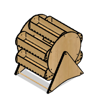
Introduction: A Storage Carousel. Complete From Design to Assembly.


This started as a learning exercise, for Fusion 360, laser-cutting, and writing an Instructable.
I have used Fusion 360 before, but only for small 3D printing jobs, where I wanted to extrude a sketch, etc. I haven't used parameters, or produced anything with moving parts before now.
Laser-cutting is very new to me. I've had my laser (the xTool M1) for a few weeks, and have experimented with engraving, and some test-cuts, but wasn't very happy with the results to begin with (more on that later).
I've read a few Instructables before, but never created one until now.
The project itself started out as an idea based around stackable storage. However, when I saw Rotunda Organiser for Hardware : 12 Steps (with Pictures) - Instructables by buck2217, I knew exactly the direction I wanted to go with it. So, I can't deny taking inspiration from that one, but I hope there's sufficient difference that no offence will be taken. It is executed in a completely different manner, and there are no similarities within the Instructable.
Please note, I have no affiliation with any of the links provided in this, they're only here for convenience.
Supplies
4mm Oak Veneered MDF, which you can buy pre-cut to 400x300mm from: 4mm Oak Veneered MDF - Laserply. (You can actually use any size/thickness of material that suits you for this, as the whole process is parameterized) [For the size I went with, 14nr sheets were needed. I cut down some big sheets to 310x300mm, but regretted making it so tight]
300mm long dowels (6 of 4mm dia. and 3 of 8mm dia. There are loads of options out there, I used: HERCHR 10Pcs Natural Round Wood Dowel Sticks, Unfinished Wooden Craft Stick 30cm Long Wood Dowel Rods for Craft Projects and Art Works, 4mm : Amazon.co.uk: DIY & Tools and HERCHR 10Pcs 8mm Dowel, Wood Dowel Rods Natural Round Wooden Craft Sticks Extra Long Unfinished Wood Rods for Craft Projects and Art Work, 30cm : Amazon.co.uk: DIY & Tools)
Wood glue (Whatever works for you. I used: Gorilla Wood Glue - Incredibly Strong Wood Glue | Gorilla Glue). Top tip - if you've got an old bottle of glue that has some left in, but it's coagulated - don't throw it out, give it a really good shake for a minute or two.
Hardware:
Laser machine (mine is the xTool M1- World's First Desktop Hybrid Laser & Blade Cutting Machine)
Software:
Fusion 360 (the personal edition works just fine for this. Fusion 360 for Personal Use Download | Autodesk)
Fusion 360 add-in: DXF for Laser | Fusion 360 | Autodesk App Store
Optional: Fusion 360 add-in: Parameter I/O | Fusion 360 | Autodesk App Store (allows import/export of parameters via a csv file)
Optional: AutoCAD LT (or any other DXF editor. Not essential, but nice to have for putting elements adjacent to each other and reducing the number of cut-lines required.)
Step 1: Decisions, Decisions, Calculations


Make some decisions about the size you want to build this. The most limiting factor is obviously the maximum size your machine can cut at, but the sheet sizes and dowel lengths are also important.
Everything I refer to in Fusion 360 was done in the 'Design' workspace.
Here are the figures or the initial parameters (entered under Modify>Change Parameters). There are a lot more parameters, but they are all handled by calculations, based on these.
NrTrays:  6
AxleSpace:  0.5   This gets added to the dia. of the dowels at each of the axle points.
Spacer:  1   The space to put between anything that move against something else.
SheetMargin:  3   How close you want to risk putting the laser to the edge of your sheets
SheetWidth:  300
MaxDowelLen:  300
SheetLength:  310
Thickness:  4   (Of the sheets)
DiaTrayDowels:  4
DiaMainDowels:  8
YOuterDimTray:  60   This is how high you want the sides of each tray.
For the calculated parameters, start by making the circular side as large as possible given your sheet size and margin, then the size of the tray sides can be calculated by fitting the number of trays you want around the circular side, to as large as possible, but staying within the side-circle, with 'Spacer' between them. Then the width of the trays can be calculated using the size of the tray sides and the height of the tray. After that, the length of the tray comes from subtracting the stand and side thicknesses (along with the spacing between them) from the maximum dowel length.
MaxDia:  min(SheetLength; SheetWidth) - ( 2 * SheetMargin )
DiaSides:  MaxDia
RadiusSides:  DiaSides / 2
ExtTraySideOverMainSide:  2 * Thickness
CtrSideToTrayDowel:  ( 2 * ( RadiusSides + ExtTraySideOverMainSide ) + Spacer ) / ( 2 * ( sin(( 360 / ( 2 * NrTrays ) ) * 1 deg) + 1 ) )
DiaTrayEnds:  2 * ( RadiusSides + ExtTraySideOverMainSide - CtrSideToTrayDowel )
ZOuterDimTray:  DiaTrayEnds * cos(90 deg - acos(YOuterDimTray / DiaTrayEnds))
MainDowelLen:  MaxDowelLen
TrayDowelLen:  MainDowelLen - ( 2 * ( ( 3 * Thickness ) + Spacer ) )
XOuterDimTray:  MainDowelLen - ( 8 * Thickness ) - ( 4 * Spacer )
Once you have the height, length, and width of the tray, the next parameters can calculate the width of the tabs
required for each. These are the calc's for the tabs along the tray's length. [I decided to go with 3*Thickness as a starting point then calculated the number which would fit, and finally used that to get an actual width per tab.]
Feel free to play around with this for your own preferences.
TabMargin:  Thickness
TabSizeApprox:  3 * Thickness
XBetweenTabMarginsTray:  XOuterDimTray - ( 2 * TabMargin )
XNrTabDividersTray:  ( round(XBetweenTabMarginsTray / TabSizeApprox) )
XTabWidthTray:  ( XBetweenTabMarginsTray / ( XNrTabDividersTray + 1 - ( ( round(XNrTabDividersTray / 2) - ( XNrTabDividersTray / 2 ) ) * 2 ) ) )
XMoveMainDowel:  ( 4 * Thickness ) + Spacer
These and a few more are in the csv file attached.
The last decision to make is which dowel-holes are going to be axle points and which are going to have the dowel fixed in. For me, I decided the holes in the tray ends and the centre of the side-circle would be axle-holes, and the holes in the outer edge of the side-circle and all on the stands would be fixed in place. I created a couple more parameters for these, with 0.5 added to the diameter of the dowels.
Attachments

Step 2: Start Designing!

Start with the tray. Using the Create>Box option, start with one corner at the centre of the design space and drag it towards the bottom-right, so the values will be positive. [I may have been missing something, but I had to type the parameter names into the dialog box rather than at the drawing, otherwise if you come back to edit the feature later, only the final value is there, not the parameter name, which means if you change the parameter, expecting it to change all related parts, that doesn't happen unless you originally typed them into the dialog box.] After creating anything, always rename it in the 'Browser' to make it easier to keep track of later.
Step 3:

After creating the tray front and back in the same way (making sure they overlap the base), move the base up a little (Modify>Move) to make sure the tabs aren't at the bottom of the sides, [I used the Thickness parameter for this] then use the Cylinder option to create the tray ends, and the dowel. To get the dowel placement right, use Construct>Axis Through Cylinder/Cone/Torus, to put a constructor at the centre of the tray's side, then move it up by half of the tray's height (YOuterDimTray/2).
[On my first attempt at this, I put the tray dowel right in the centre of the tray's side, which was a mistake. Luckily I'd cut and built only one tray before realising it would overbalance as soon as something was put in it! So, I had a re-think after that, I wasn't sure if the trays would pass each other if they were hanging below their pre-calculated positions, but it turns out that isn't an issue - as long as the dowels are still in the same positions on the side-circle. It then looks like a Ferris Wheel (which now makes much more sense).]
Step 4:

Since the dowel-holes here are going to be axle-holes, they need to be formed separately (as opposed to using the dowel as a cutting tool) to give the dowel room to move. [I added 0.5mm to the dia. of the dowels to get the axle hole's dia. but 0.25mm would probably have been sufficient] Do some test holes in a scrap piece of your material to gauge the size in which your dowels will turn easily without moving about too much.
Make sure you expand the 'Objects To Cut' drop-down, and make sure it will only be cutting through the objects you want it to.
Step 5:

The next stage was to start on the tabs. This is where the pre-calculated parameters really come into their own. Use Construct>Offset Plane and offset it from the inside of the tray-end at the origin, by 0mm. Then create as many more as you need to get all the way along the tray, always offsetting from the previous plane by XTabWidthTray. If the calc's worked out, the last one created in this way will match up with the inside of the other end of the tray. Select the first plane in the browser, then hold shift and select the last plane, then left-click on the name of the top one and rename it something like 'XCutPlanes' (all those selected will be renamed with incremental numbering). Without changing the selection, right-click on one and select 'Create Selection Set'. Name the selection set the same, and then hide them (press 'V' to hide/show selected objects).
Repeat in the same way for each of the remaining two dimensions (make the inner tray side (front or back) one starting point for ZTabWidthTray, and then make the top face of the base the last starting point for YTabWidthTray). This is the most tedious part, but it's worth it.
Select the tray base, front, and back, then choose the tool Modify>Split Body. In the dialog box click Select for the Splitting Tools, and select the first and last of the XCutPlanes, tick Extend Cutting Tools, and click OK. Repeat with the tray-base alone and the first and last of the ZCutPlanes.
They should look like the images above.
Step 6:


Now select the two end pieces of the base, and use all of the ZCutPlanes to split them up. Select the two side pieces of the base, and split them using the XCutPlanes. Finally select the four end pieces of the two sides and split them using the YCutPlanes.
You'll end up with the first image above, and then you can select every other tab (click on one, then hold shift and click on the others), then right-click and select 'Remove' until you have the second image above. At this point it's important to realise that the sides do not have the tab-holes even though it looks like they do in that second image.
Step 7:

Now re-join the tabs to their respective parts: Choose Modify>Combine, select the base, and then the tabs surrounding it, make sure the Operation is 'Join', and 'Keep Tools' is de-selected. Then hit OK.
Repeat with each of the sides.
Step 8:


The final step for completing the tray is to cut the tab holes in the sides and ends. Start by choosing Modify>Combine, with a side selected as the Target Body, and the base selected as the Tool Body. Make sure the Operation is Cut, and that Keep Tools is selected. Hit OK. Repeat this with the other side, and then the ends - select an end as the target, and the base+sides as the tools.
Your tray is complete!
Step 9: Circular Sides


For the sides, create another cylinder, this time centred on the tray dowel, with the usual thickness, and a diameter of DiaSides. Move it downward by CtrSideToTrayDowel, and away from the tray's end by Spacer. Put a constructor at the centre with Construct>Axis Through Cylinder/Cone/Torus (selecting the face of the outer edge of the side for this). Then use that constructor as the centre of a new hole. Just as the previous one, except for the size - DiaCtrAxleHole.
Select every part of the tray, especially the dowel, and then choose Create>Pattern>Circular Pattern. Click on the axis selector and then use the axis constructed earlier. Make sure Distribution is set to Full, and set the Quantity to NrTrays.
When you hit OK, you'll have the trays distributed around the side, but they will need to be rotated around their dowels if you want them to look as if they are hanging correctly (it only affects the appearance of the design, and has no effect on the outcome, so you could leave them as they are if you like).
Now, select the side, and open Modify>Combine. This time you'll be choosing the tray dowels as tools, and cutting into the side (remember to have Keep Tools ticked).
Create the centre dowel now, using the same axis and the parameters DiaMainDowels and MainDowelLen, then move it by XMoveMainDowel, so it looks like the second image above.
Step 10: Stand


For the stand, we could just use a block, but I wanted something with a bit more shape to it, so started with a sketch.
First select everything we have so far, and choose Modify>Move, Select the 'Point to Position' option, and select a point at the top centre of the centre axis of the nearest side (it'll snap to this when you get close). Set X,Y, and Z to 0, and hit OK.
Now click on Create>Create Sketch, and choose the YZ Plane as the sketch plane. Turn Snap on in the Sketch Palette dialog, and choose Create>Line. Click on the bottom left tray dowel, the top centre tray dowel and the bottom right tray dowel, then press the Esc key so you have a pair of lines like an arrow head. [Now a part that had me baffled for the first few minutes.] You need to remove the constraints from the end-points of those lines, or you won't be able to move them later. Right-click on one of line end-points and select Delete Coincident, repeat for each of the three points.
Next to get that nice rounded top, choose Modify>Fillet, select both lines, and drag the top of the fillet until you have a shape you like. In my case I changed the value to 6*Thickness. Notice that this also gets a new point added at the centre of the rounding. Now select all three points and choose Modify>Move. Use the 'Point to Position' option, click on the Point box in the dialog, and choose that top centre point as the start point. Set Y to 0 (X and Z should already be 0) to place the curve in a nice position around the centre axle.
Now move the two bottom points individually. Select the bottom-right one, Modify>Move, Point to Position, choose the point itself as the Point, then move it to a position you like the look of, or use Y = -CtrSideToTrayDowel - DiaTrayEnds - ExtTraySideOverMainSide - ( 6 * Thickness ); Z = CtrSideToTrayDowel + ( DiaTrayEnds / 2 ) + ExtTraySideOverMainSide + ( 3 * Thickness ). If you choose your own position, take note of the values for the next point. Repeat the move for the bottom-left point, but use the negative of Z. [ Z = -CtrSideToTrayDowel - ( DiaTrayEnds / 2 ) - ExtTraySideOverMainSide - ( 3 * Thickness ) ]
Now create a line between the two bottom points. You can take the edge off the resulting corners using the fillet tool if you like. To make a space as a hand-hold at the bottom, use Create>Rectangle>Center Rectangle. If you hover near the centre of the bottom line, it will show a triangle next to it when you can snap to the centre of the line. Make it whatever size you like (you can safely ignore the half that appears below the line) and fillet the top corners.
If you now click within the main sketched shape, it will select the shape we need, and you can then click on Finish Sketch. Next choose Create>Extrude, type Thickness into the Distance box, and make sure that the Operation is set as New Body. Once you have the new body, move it away from the circular side by Spacer.
Select the main dowel, and choose Modify>Move\Copy, make sure Create Copy is selected, and choose Free Move as the Move Type. Drag it towards the bottom left corner of the new body. Once it's in a position you like, select the new dowel and choose Create>Mirror. For the Mirror Plane choose the XY Plane.
Finally, select the stand body, and choose Modify Combine, select the three main dowels as the Tool Bodies, and select Cut as the Operation, making sure that Keep Tools is ticked, then hit OK.
That's it as far as the required elements of the design are concerned. If you want to make it look fully formed on screen, copy the stand twice, moving each one by Thickness, then select the circular side, and all three parts of the stand, mirror them on the YZ Plane, then move the new parts to the opposite end of the dowels.
Step 11: Create DXF Files
This is where the add-in DXF for Laser comes in.
Choose Create>Save DXF for Laser Cutting. Select the top face of the tray's base as the first face, and edit the Laser Kerf value to suit your own laser [for the M1 it's 0.08mm], and hit OK, a save box opens for you to save the file.
Repeat with a tray side (front and back are identical so only one DXF file is required), a tray end, a circular side, and a stand part.
That's all you need for the DXF files.
Step 12: Edit DXF Files


This is optional, but there are a couple of tweaks which can save material.
Open AutoCAD [LT 2019 in my case], and click on the Open File icon at the top of the window. Open the dxf file containing the tray side. [If your setup is like mine, you'll need to zoom out quite a bit to actually see the drawing.]
Press Ctrl+A to select everything, choose Home>Modify>Copy and then click on the top-right corner (hover until the cursor shows 'Endpoint', so you know it's going to snap there), now click on the bottom-right corner in the same way. Select the line between the two by clicking on it, and press Del to delete it, there will still be another line between them. You now have a drawing that puts the two tray sides right next to each other, with only one laser cut to separate them.
Save it as a DXF file [AutoCAD LT 2018 DXF format worked for me].
Depending on the size of your machine's cutting area, or the size of the material you have, or the laser cutting software you're using, the next step may be completely unnecessary. For xTool Creative, if you rotate something, it considers the object's original bordering rectangle as part of the object, and if that rotates out of the working area, it refuses to process it, even if the object itself is still entirely within the working area. [I had to rotate the stand to fit it inside the material, so that rotation had to be done within AutoCAD.]
Open the dxf file containing the stand, select all, and choose Home>Modify>Rotate. Click on the centre of the top-centre hole (hover until it says Center), and then rotate until it's aligned how you need it. Save it.
Step 13: Cutting

Before you start cutting, make sure your laser cutter has the optimal cutting settings. [Another one that had me pulling my hair out for a while.] One aspect that isn't commented on enough is the thickness/distance setting. [I had assumed that using auto-measure, or typing in the actual thickness, would be all that was required, and the rest of the testing would be based around power/speed/passes. Not So!] With any new material, first set power at 100%, speed at about 20%, and passes at 1. Then make some test cuts (they don't need to be long or deep) at various different values of thickness (in Laser Flat mode) or distance (in Open Plane mode). You are looking to get the finest line possible without changing any other settings than thickness. [I found that 3mm was the best thickness setting for my definitely 4mm thick material.] Once you have that, then you can start testing to get a cut that goes all the way through. At this point you may want to use a shape such as the maple leaf from the Shape menu, make it about 25mm wide. Keep the power at 100%, and passes at 1, unless you get to either end of the speed limit. If the lowest speed isn't sufficient, increase the passes, if you get to the fastest speed, decrease the power. Once the shape pushes out easily without any burn marks around it, you have your settings.
Once you have those settings, it's plain sailing. Put your fresh material in, load the dxf files (using 'Image' in the case of xTool Creative Space). When you load these files, you'll find the tab holes for example aren't grouped with the tray sides, so select each element by dragging a selection rectangle across it, and hit the Group icon so you can move them together. Get everything aligned in the most material saving way you can and then select all (Ctrl+A) and choose Cut. Set the values you need, and hit Process.
Repeat until complete!
Step 14: The Assembly


Putting it all together is straightforward, and as long as you've been following along, it should be obvious what goes where. So, just some tips here:
Don't forget to trim the tray dowels to the length decided by the parameters earlier.
When pressing the tabs into the tab-holes, it can take precise lining up and a lot of pressure to get them fully together. This is a good indication that your cutting settings were ideal, and no glue is necessary for the trays at all.
Glue between the 3 stand pieces, and put dowels into the holes to keep them in position relative to each other. Glue at each dowel hole which isn't an axle hole (where the tray dowels meet the side, and where the main dowels meet the stand). Being careful to deal with any excess which could get against other parts.
When you put the sides on, and when you put the stands on, don't forget to put something of thickness 'Spacer' between them and other parts, to keep them from rubbing against other parts when it's turning. Anything flat, and of the right thickness, will do here. If you don't have some thin balsa wood you could just use small piles of paper.
That's it, you now have a Storage Carousel. :D Mine is pictured under my model painting station.

Grand Prize in the
Organization Challenge


17 Comments
2 months ago
Nice idea. I have a suggestion. Would it be great to add a center gear (and a handle) and gears on the baskets that keep the baskets in the correct orientation. When you rotate the wheel the baskets change position however keep their orientation. With this method you avoid that when some basket get stuck it throws everything on the table or in the mechanism. If a basket get stuck, the whole mechanism won't rotate because of the gear mechanism.
Reply 2 months ago
Hi codebeat, have you built this? I haven't had any issues with sticking. Maybe you haven't allowed enough space between the trays and the sides. It may be worth trying some wax or spray-lube at the axle-holes. I suspect that adding gears would make it more likely to stick, not less.
3 months ago
Well done, I got second prize for my version (you had better make me one of yours!) 😂
3 months ago
Well done, looks sleek! :)
Tip 3 months ago on Step 14
One additional point: that spacer material, mentioned at the very end, is only temporary, until the glue is dry.
3 months ago
Clever, clever design that's very useful. I've made many boxes using 0.71" hardboard from Home Depot. After tuning the kerf setting on the laser, my boxes fit together so tight, I don't use glue. I use the F360 finger joint add-in. Its very flexible and quick. However its not parametric, so changes made to your design (like width and length, earlier in your timeline) don't get updated by this plug-in. So you have to delete the finger operations and re-apply. Your approach using all the equations is parametric (my first F360 project did it this way as well). Thanks for the instructable - my wife wants one for her oil paints.
https://github.com/FlorianPommerening/FingerJoints
3 months ago
I'm going to have to try this on my laser cutter (I have a Glowforge). This looks perfect for holding the things I need to work on my miniatures. I do have a question. In the last picture, you have a red stand that this sits under. Where did you get that stand? I've been looking for something like this since I have major back and neck issues and have been looking for something that I can use to raise my work surface when I need to do detail work that currently requires me to bend forward (like putting decorations on a 1:12 scale clay cake or icing 1:48 scale clay cookies). Thank you!
Reply 3 months ago
It's a Duronic Laptop Stand DML121, which can be bought from Amazon: https://www.amazon.co.uk/Duronic-DML121-Multi-Use-Adjustable-Ergonomic/dp/B071ZN2H73
Reply 3 months ago
I'm in the US, so the Duronic is kind of expensive here. I think I'm going to try this one, since it's about $10 less but seems to be of a similar design. I can always return it and get the Duronic if it doesn't work out.
https://smile.amazon.com/gp/product/B01C80K7X4/ref=ewc_pr_img_1?smid=A3E3P0NQDIEF4T&psc=1
Reply 3 months ago
THANK YOU!!! I never thought about using a laptop stand. I'm off to buy it.
Reply 3 months ago
Hi, it's actually a laptop stand I've had for years. I use it for exactly the same reason (except for me it's models, not cakes. :D ) I'll see if I can find any emails relating to where I bought it.
3 months ago
I just want to say this is a friggin awesome instructable. The post on laser cutting and building the thing would be good but the fact that you walked through the design process in fusion, mistakes and corrections along the way, so that anyone could follow along is fantastic. Kudos to the author and I can’t wait until I have some free time to walk through this.
3 months ago
Great design and write-up; I'll save this for the day I get a laser cutter.
Reply 3 months ago
Thanks.
3 months ago on Step 13
Really cool! I have a BOSS Laser LS2436, I would love to try this!
3 months ago
Nice, I've recently bought a cheapo Chinese laser cutter but am still very much at the learning stage. Can you tell me what laser you use as I want to cut 3mm mdf.
Also no offence taken ay your superior copy 😊
Reply 3 months ago