
Introduction: Upgrade Your Maglite With a Rechargeable Battery and LED!


Hello fellow makers,
In one of my most popular Instructables I showed you how you can upgrade your Maglite to be rechargeable and also make an LED bulb for it.

DIY Maglite USB Rechargeable 18650 and LED Upgrade
Within the instructions I mentioned the higher power upgrades I do on some of my flashlights and a lot of you guys were really interested in that.
Unfortunately a lot of the parts I use in those are difficult to reproduce so I never got around to making an Instructable about them, that's until I was changing a taillight bulb and saw something wonderful!
The automotive industry blessed us with a wonderful piece of technology that will simplify the whole process.
I also redesigned the whole battery system to make swapping batteries on the go a possibility.
Let's get making...
Step 1: What You Will Need:


To upgrade your Maglite you will need the following:


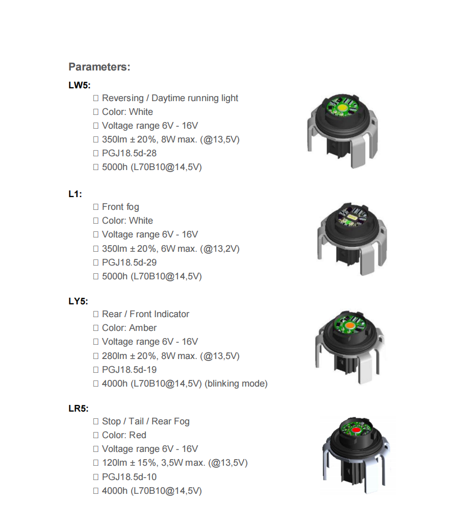
- Osram XLS bulb
Amazon - example (will update once I find a reliable online source)
These seem to be found on a lot of newer Japanese cars especially Toyota's.
I have also found some alternatives that come in the same regulated size like the Luxeon LxN range aswell as some L5W's from Koito.
![]()
- Access to a 3D printer
- Li-ion charging plus step up board
- 24mm zinc or brass washer
- 6mm brass tube
- 1amp Flashlight switch
- 22AWG stranded wire
- Multimeter
*As an Amazon Associate I receive a small percentage from sales made through provided links at no cost to you, this helps fund future projects.
Step 2: The Osram XLS:

Specifications of the XLS Series:
Step 3: Design and Print:

I completely redesigned the electrical components of the flashlights so that you are able to swap the rechargeable battery between different 2-D and up Maglites.
The components are all designed in Tinkercad using only basic shapes to make customising them easier to fit your needs. All designs are open to the public so you can modify as much as you want.
It also makes it possible to have a few charged backup batteries that can be swapped in on the go.
There are two variations of the back cover available depending on if you are able to print small pieces or not, I had a lot of trouble in our heatwave to get the top of the cover printed correctly so I decided to add one without that piece and just fill the void with some black hot melt glue.

The design includes a battery spacer so that the one battery module can be used in Maglite 2-D to 6-D without altering.
As some of my older Maglites have badly corroded switches I also designed an adaptor to make use of easily available flashlight switch replacements.
The parts are printed using PETG just to avoid deformation within the flashlight when it's left in high heat environments.
Attachments


Step 4: The Battery Spacers:


We will start by assembling the battery spacer.
The adaptor files I included is for a 50mm long body, that will roughly give you a standard D-cell battery. You can easily alter the design in Tinkercad to fit your specific flashlight so you don't have to print 4 loose adaptors if you have a 6-D Maglite you can just print a single long one.
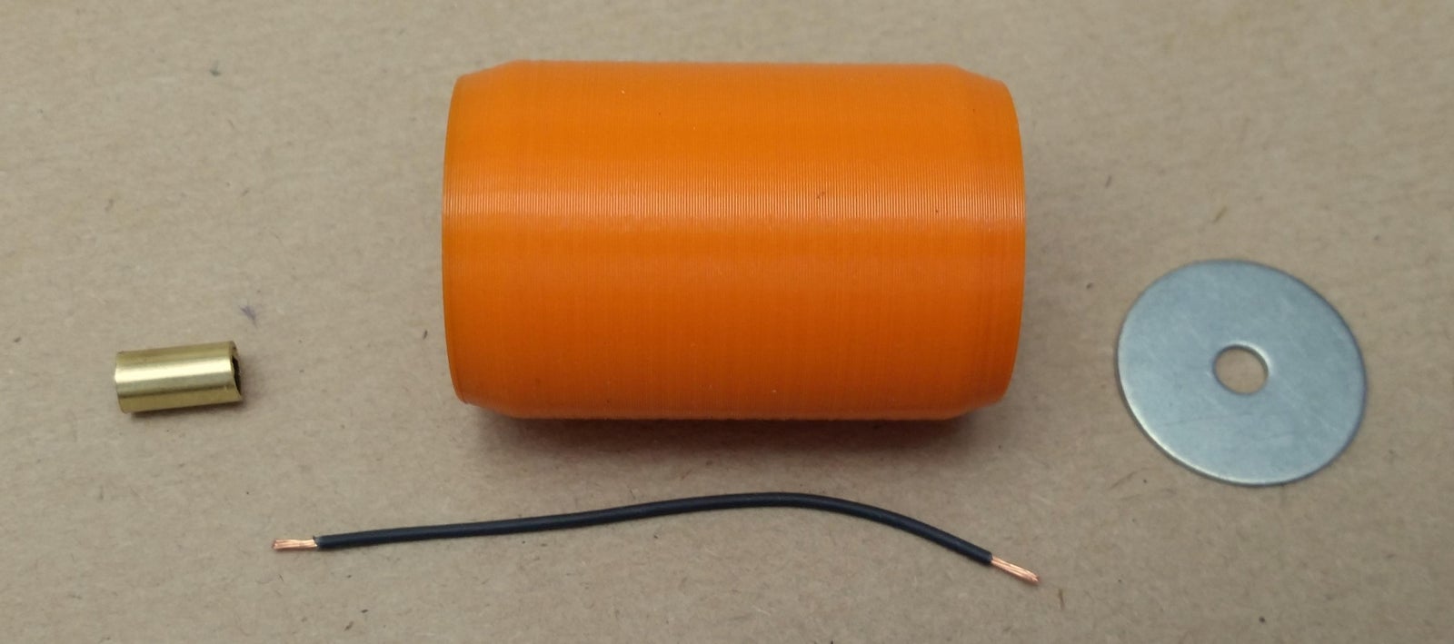
Start by cutting a piece of wire approximately 70mm long (this is for the 50mm adapter if you make the adaptor longer you just need the wire about 20mm longer to make soldering easier) then solder the one end of the wire to the 24mm washer, feed the wire through the adaptor and heat set the washer into the cavity using your soldering iron.
The other end of the wire gets soldered to the inside of your 6mm brass tube and can then also be heat set into the adaptor. Now if your soldering game is on point you can close up the tube with some solder and make a nice cap or you can just leave them as is.
Check them for continuity and they are ready.
Step 5: The Battery Module:

Now it's time for our new battery module.
This part consists of our 18650 lithium ion battery, the lithium charger and a step up module so we can control the output voltage all in the size of two D-cell batteries.

Following the schematic we first solder on two wires to the battery negative, one will go to the BAT- on the charging board and the other will go to the washer on the bottom of the module. Next we solder on a single wire from the battery positive and that goes to BAT+ on the charging board.
On the step up side of the board we need to solder on a piece of wire to the OUT+, this will be soldered to the 6mm brass tube that will create our positive terminal of the module.

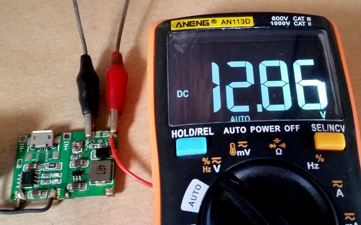
Using a multimeter you can adjust your output voltage of the battery module by turning the small potentiometer on the board, I set mine to 12.8V.
While it was originally intended for the Maglite upgrade I find myself using it quite a lot in my workshop especially with older electronics.

Step 6: The Replacement Switch:

This step is optional as you can reuse your existing switch by just cutting off the post where the original bulb was mounted on and soldering a wire to the contact of the switch.
To assemble the switch you simply need to solder a wire to the one side of your switch that will go to the LED and another wire that will go to the positive contact as shown in the picture.
On my switch I used a brass screw just for a little more surface are but you can simply use the 6mm brass tube.
Step 7: Prepare the Osram XLS:

There is very little that needs to change with the existing as it is pretty near perfect for the application.
As I don't have the original connector I'm replacing them with a normal 2.54mm 2 pin female header and it works great with a nice snug fit.
For the negative I simply soldered the wire onto the heatsink as this will be against our Maglite body connecting to the battery modules negative.
I will be soldering the positive wire onto the wire from the switch but you could also use 1 pin female header connectors and simply plug it in when assembling.
I covered the connector in black hot melt glue to protect it against vibrations.

And finally I used a sharp hobby knife to remove the flanges around the LED that was originally intended to secure the bulb into the taillight.

That's it your bulb is ready to be installed.
Step 8: Assembling the Flashlight:


We now get to the final assembly of our flashlight.
Starting with the switch depending on the tolarences of your 3d printer it will push in from the battery side of the Maglite with some friction untill it hits the retaining circlip in the front (make sure to depress the switch when sliding it in), if you feel the switch is too loose you can just add a drop of weak adhesive behind it through the switchhole in the flashlight befor pushing it back into place.

Now with a piece of sandpaper sand away the anodising around the inside of the flashlight at the bulb end as pictured, this will ensure good contact with the battery negative.

Using something like a pipe (I used a wrench socket) that fits around the plastic surrounding of the LED we can start tapping the LED module into the flashlight. Depending on the LED you received you might have to slightly bend in the heatsink of the bulb inward until it will fit. Continue tapping it in until there is only 5-7mm of the bulb sticking out of the top.
The LED bulb will go in snug and that's good for electrical and thermal connection with the Maglite.
As with my other high power mods to Maglites the hole of the reflector will need to be enlarged. I first cut off the back with a hacksaw so that the hole is just slightly too small then I sneak up on the correct size with sandpaper placed on a sheet of glass. This gives a really good finish.

Now you can screw on the lens, insert the battery module and adaptor and give it a go!
Step 9: Enjoy!


I'm more than happy with this upgrade, it is much easier than my previous high power upgrades and the 8W output from these Osram bulbs exceed a lot of my Chinese 10W Cree bulbs plus they already have a brilliant control circuit built in!

I hope you guys find this Instructable useful and if you have any questions please feel free to leave me a message or comment bellow.
Please share your own creations with us by clicking the "I Made It" button below.
Happy making!
---

Judges Prize in the
Make it Glow Contest


12 Comments
7 weeks ago
Have considered using a usb C connection on the side of the flashlight to charge the battery pack ?
Reply 7 weeks ago
Hi, I recently found a much smaller USB C version of the charging/boost board that will be an easy swop.
7 weeks ago
Will this all fit in a 2C cell flashlight?
Reply 7 weeks ago
Hi, when I get a chance I will try to model one for the 2-C. The biggest problem might be the charging board but I've found a much smaller version that it can be replaced with.
Question 7 weeks ago
Do I understand correctly that the input to these modules can vary from 6 to 16 volts? That's about the range of the output on my model T magneto. It has been impossible to find a bulb that will light at 6 volts and not burn out at 16. Could this be it?
Answer 7 weeks ago
Hi, I've tried the bulbs with 9-14 volts and they work great. I'll give it a try at 6v too and see how they work and get back to you. :)
7 weeks ago
This looks great! Any idea where to source the bulbs? In a 6D flashlight, could you fit 4 batteries and ditch the spacer?
7 weeks ago
This is a great idea, but I do not have a 3d printer. I will probably try pvc pipe and build up something with the same function.
Also would like to try using the charging board to gang charge battery powered under cabinet lights. If that works, I will evade using 120 volts. Being able to wire illumination with doorbell wire is a safe code free way to go.
7 weeks ago
This way the led does not uses the the reflector. This special reflector give's the maglite his unique feature, the long range beam.
Now you got a useless wide short light source..
7 weeks ago on Step 9
I presume it’s ok to use 2/3 battery units in 4/6 cell torches if you adjust voltage down 6.4/4.3v to give extended usage?
2 months ago
This is great! Love it when you find a solution in a place you weren't looking for it :)
Reply 2 months ago
Thank you! This was a very lucky discovery as everything works so well together.