
Introduction: An Educational Game: Stack-0!
We are a team of four students from Piedmont Hills High School: Jocelyn Lee, Kevin Kiattinant, Shruti Raghu, Youjia He.
Are you laying around your house with nothing to do? Did your parents ban you from playing video games because they weren’t educational? Are you looking for a fun game to play that your parents would approve of? Well we’ve got just the thing. Introducing Stack-o; the first game to combine fun and architecture. But wait, there’s more, there are TWO versions of this game for you to play. In the regular version you and your friend have to stack the blocks to get the highest structure, with a little bit of randomness sprinkled in with the roll of a 12-sided dice. You can also play in Earthquake mode, where you stack the blocks to not only be tall, but also to have enough stability to withstand a stimulated earthquake!
Supplies
----<>----
- 4 Rolls of PVA filament
- 3d Printer
- Autodesk Fusion 360
- 4 mm thick skewers
- Springs
- Sharpie
- Pliers
- Time!
----<>----
Step 1: Designing the Blocks

----<>----
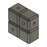
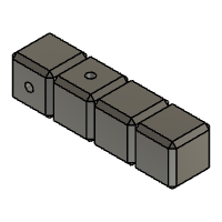
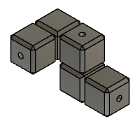
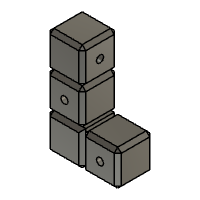
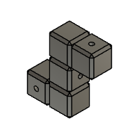
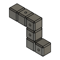
Start by making the rough shapes in Fusion 360. Each block unit should be 1x1 inch squares. Make sure to make the lines in between the shape to make each individual square. Make multiple different shapes.
Step 2: Extruding the Blocks


Extrude all of the squares individually by clicking 'New Body' when extruding each block. The sketch might disappear when you make the first extrude so make it visible again. Make sure to check that the extrude operation doesn't say "join" each time you extrude. If it joins, the chamfer won't work correctly.
To make another cube on the side click on the preferred face and make an extrude (you might have to make it distance -1 depending on which face you choose.)
Step 3: Chambering

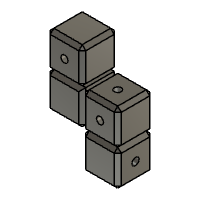
Click all of the exposed faces on the blocks. They should all be separate faces if 'New Body' was selected when extruding each block separately. Then click the chamfer tool. Chamfer all sides by 0.1 inches (You can change the chamfer size if you want it to be bigger or smaller.)
Step 4: Adding Holes


Add 0.197 inch (5mm) wide holes throughout the block on any faces you want. The holes can be 0.5 inches or 1 inch. Make sure that the holes are positioned in the center of the individual square block. Make sure that the hole type, hole tap type, and drill point are as indicated in the photo.
Below are the Fusion 360 files of the different types of blocks that were printed for the game.
----<>----
Attachments


Step 5: Measuring the Sticks


----<>----
Start by measuring out 1 inch sections on the sticks and mark them with a sharpie. Cut them at each mark.
Step 6: Finishing the Sticks

Repeat these steps with two other sizes, which are 1 1/2 inches, and 2 inches. Make sure to make approximately 30 of each stick.
----<>----
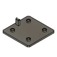
Step 7: Making the Clamp

----<>----
Ensure that the file is in millimeters (mm). Start by making several rectangles that resemble a backwards C. The length of each side should resemble the picture shown above. Extrude it approximately 10 mm.
----<>----

Step 8: Making the Earthquake Platform

----<>----
The earthquake platform is to stimulate an earthquake in the Earthquake mode. It consists of springs and 3D printed parts.
Step 9: Designing the Platform

There are three parts to the platform:
- Top platform
- Bottom platform
- Crank
Everything in this design is in INCHES
The constraint of the platform is to be able to fit the biggest block, thus, it will depend on the types of blocks you make (as well as if it can be printed within your 3D printer).
The size of our platform was 5 x 5 inches, as the biggest block we have has a length of 4 inches.
Another constraint is the size of your springs. Make sure to measure the height and width of your springs to modify your own platform.
The size of our springs were 0.5 inches wide (the thickness of the springs was 0.1) and 3 inches tall.
Step 10: Bottom Platform


- In sketch, draw a square of 5 by 5 inches.
- using shortcut "D" for dimension tool can help speed the overall process
- Extrude the sketch by 0.25 inches
Step 11: Bottom Platform Cont.


- Create another sketch on the extrusion, draw concentric circles that are 0.6 and 0.5 and 0.4 inches (this is the dimensions to place the springs, so modify accordingly)
- Holding shift, select the circles and copy them (ctrl + c)
- Then paste (ctrl + v) it three other times
Step 12: Bottom Platform Cont.


Dimension the center of the circles 1 inch relative to each edge of the extrusion.
Step 13: Bottom Platform Cont.


- Extrude the circle that is 0.4 in diameter a height of 0.15 inches
- Extrude the area between 0.6 and 0.5 circles a height of 0.2 inches
Step 14: Bottom Platform Cont.

Optional: Chamfer the four edges by 0.2 inches
Step 15: Bottom Platform Cont.

Create a sketch in one of the vertical planes (XZ or YZ)
- Draw the shape in image 2
- Project supporting sketch lines (purple) with the shortcut "P"
- Notes:
- The circle and arc are concentric
- The arc is tangent to the vertical lines
Step 16: Bottom Platform Cont.


- Extrude the sketch (excluding the circle) for 0.75 inches
- Cut the extrusion by 0.25 inches
The bottom platform is done, the Fusion 360 file is attached below
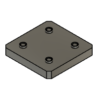
Step 17: Top Platform

Start the top platform the from the same point as Step 11 (or 12 if you chamfered it)
Step 18: Top Platform Cont.

Flip to the bottom face and create a new sketch.
- Draw a circle of 0.197 inch diameter
- Constrain the center of the circle to the edge of the platform by 0.5 inches on either side.
Step 19: Top Platform Cont.

- Cut the sketch by 0.15 inches
- Using the rectangular pattern tool, select the previous extrusion and enter in the correct information to create a 4 x 4 pattern of extrusions (look in the image to fill out related prompts)
Step 20: Top Platform Cont.

Make a new sketch on the top face
- Project the outer edge of the platform
- Using the offset tool, offset the outer edge to be 0.15 inches
Step 21: Top Platform Cont.


Extrude the sketch. You'll need to extrude it twice (by 0.5 inches and 0.25 inches)
Attached below is the file for the top platform design
Step 22: Crank
This was the most difficult by far to design, as this piece is so small yet there was a lot of force being exerted on it by the user. I do not yet know how to assemble within Fusion, so having all the pieces fit and do their part all came together within the crank.
Step 23: Crank Cont.

Start a sketch
- Draw an arc connected by a line that is 1.5 inches
- Draw a circle that is 0.15 inches in diameter
- the circle is tangent to the line
- the circle's center is coincident to the dotted line
- the dotted line is vertical and the endpoint is the midpoint of the arc
Step 24: Crank Cont.

Extrude to a height of 0.2 inches
Step 25: Crank Cont.

Start a sketch on the surface of the extrusion
- draw a circle of 0.197 inches in diameter (*dimension in image is wrong)
- center of circle is 0.5 inches away from the center of the semicircle
- center of circle is 0.3 inches away from the origin
Step 26: Crank Cont.


Cut the circles drawn in step 21 and 23 by 0.15 inches
Step 27: Crank Cont.

Fillet the edge of the semicircle by 0.3 inches
----<>----
Below is the file for the crank

Step 28: The Dice

----<>----
Since there are 12 different blocks we decide to use a dodecahedron to randomize your block choices while playing the game
Step 29: Making the Dice 1

Step 1:sketch a hexagon on the xy axis
Step 2: exit the sketch and patch the hexagon
Step 3: Duplicate the patch
Step 30: Making the Dice 2


Step 1: select the second patch right click and select move/copy
Step 2: use the rotate feature and type in angle: acos (-1/sqrt(5))
Step 31: Making the Dice 3

Step 1: selected the angle face and use the circular pattern
Step 2: rotate on the z axis with 5 faces
Step 32: Finishing Up the Dice 4

Step 1: select all the sides and press move/copy then make a copy
Step 2: then change the z angle to 180
step 3: then choose the point to point tool and put the points together to finish yo the dice
step 4: last step! add numbers!
----<>----

Step 33: Some Mishaps Along the Way

----<>----
This project wasn't easy, as there were many prototypes made and issues pertaining to each of them.
One of the most time consuming issues was printing the platform, as it was warping multiple times that were attempted to print. The thinner the platform, the more they warped, so the second prototype is much thicker than we would've liked.
With the clamp, there were also issues regarding the tolerances being too tight, and the screw broke multiple times due to insufficient infill. In the final version, we had to lubricate it with soap.
----<>----

First Prize in the
Game Design: Student Design Challenge


Comments
Tip 4 weeks ago
Background